Technical information about the '76 to '79 Cadillac Seville. Subjects are "EFI Diagnosis", "'76 - '79 body parts", "Frame diagram" and "Electrical troubleshooting".
Diagnosis of problems |
Back to the top |
DIAGNOSIS OF PROBLEMS
The diagnostic “decision trees” and accompanying explanations contained in this manual are designed to help solve complaints on all fuel injected Cadillac vehicles, 1975 to 1977. The complaint symptoms are closely defined so that only the most likely failures will be investigated and time is not wasted on components which normally do not cause the complaint. Select the complaint which is most descriptive for the vehicle and progress through the “decision tree” until the problem is located. Steps of the “tree” which require testing or explanation are described immediately following each “decision tree”. The explanations are keyed to the appropriate points of the “tree” by the numbers in parenthesis which correspond to the numbered explanations.
Frequent references will be found in this manual to the Electronic Fuel Injection Analyzer J-25400. However, the use of this tool is called for only after a decision has been made that its use is required. Refer to appropriate model year shop manual for analyzer instructions. Many components can be functionally tested with the “quick checks” presented here.
The procedures presented here incorporate other engine systems in addition to EFI since many complaints are caused by improper operation of these systems, and not necessarily the EFI system.
Electrical and vacuum circuits for all fuel injected cars, 1975 to 1977, are presented at the back of this manual to aid diagnosis as small changes have been incorporated from year to year which often affect diagnosis. When specific circuits need investigation, reference will be made to a circuit number (807,827, etc). Circuit number is shown in Figs. 18 through 22 preceding the gage and color code.
The information presented in this manual represents the service diagnostic knowledge gathered to-date. However, the procedures may be supplemented or updated at any time.
DIAGNOSTIC CARD
Accompanying this manual is a diagnostic card listing the symptoms and causes explained in detail on the following pages. It is intended to serve as a reminder of the probable causes of a complaint condition once this manual has been frequently used. The card lists the causes of each condition in an increasing probability of failure based on field experience. For any symptom, the cause identified by #1 should be investigated first, followed by #2, #3, etc. Because the chart represents actual field experience, the sequence of diagnosis may differ slightly from the most logical sequence presented in this manual. All potential failures which contribute to or cause a specific problem are investigated in both diagnosis forms. If all of the causes have been investigated for a particular symptom, and the problem has not been solved, it is most likely that the problem has been missed and that a review of this manual is needed.
When using the diagnostic card, select the problem symptom which most accurately describes the conditions on the car, It is important for the serviceman to evaluate a problem for himself so that the problem and its severity can be experienced, If at all possible, try to talk to the owner on intermittent problems, as he has the best information on exactly when the problem occurs.
SYMPTOM DEFINITIONS
Because of the specific complaint symptoms presented, it is important to review and understand the definitions and abbreviations listed below:
- Stalls - The engine stops running. It may occur at idle or while driving.ABBREVIATIONS
TPS - Throttle Position Switch (also called Acceleration Enrichment Switch)Stalls after start - Cold |
Back to the top |
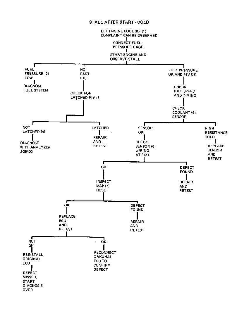
This condition is defined as a situation where the engine is cold and when started, stalls either immediately or as a driveaway is attempted.
1. The first step of any diagnosis should be to confirm that the complaint condition does exist, and to observe its severity. Obviously a cold complaint can only be observed when the engine is cold.
2. Normal fuel pressure is shown in Fig. 1. Fuel pressure which is low or was normal when the engine is started, but falls off as the stall develops, can be either an electrical or a fuel system problem. To eliminate the electrical aspects, repeat the stall with the Analyzer J-25400 in step 20 (monitor) and observe the speed sensor, fuel pump, group 1 and 2, and ignition ON lights. Proper operation of the indicator lamps is as follows:
a. Trigger lights - these lamps indicate the connection made by each set of speed sensor contacts. The lights should blink alternately ON and OFF with equal intensity and with a constant rhythm. A lamp OFF, double blink, or a bright or weak blink indicates a speed sensor malfunction.If all lights operate normally as the stall develops, diagnose the fuel system as described on Pages 44 thru 49 If no defect is found, replace the ECU and retest.
3. A “latched” FIV is a condition where the retainer clip becomes “latched” below the seat, thus holding the valve in its closed off position, Fig. 2. To check for this condition, remove the valve and visually inspect.
NOTE: The white substance found on the bottom of the heater is a heat transfer compound and does not indicate a heater failure.
A latched FIV can occur either as a result of a heating element malfunction or removal of the valve.
4. A good fast idle valve should be subjected to the electrical tests described for Analyzer 1-25400.
5. During cold operation the coolant sensor signal (low resistance) is used by the ECU to provide a richer pulse width. The resistance of the sensor can be determined with Analyzer 1-25400 in step 10, or can be determined with a VOM (volt-ohm meter) at the connector. A defective sensor is indicated if the resistance value does not compare with the values shown in Fig. 3.
6. If the sensor checks OK, it is still necessary to insure that the resistance signal is being delivered to the ECU. This can be accomplished with Analyzer J-25400 or by probing terminals “D” and “G” of the red 9 way connector with the VOM. This value should be the same as that measured at the sensor.
7. A leak in the MAP hose will alter the signal received by the ECU and may be severe enough to cause stall. To check the MAP hose, disconnect the hose at the throttle body and connect a hand vacuum pump such as 1-23738 to the hose, Develop a vacuum of 15” in the hose and check for leak down.
The MAP hose should also be inspected for kinks or restrictions at the throttle body, ECU and in the harness where the nylon line passes the exhaust manifold. If no defects have been found at this point, a new ECU should be installed on a trial basis.
A damaged hose can be replaced without replacing the entire line by splicing in a section of hose which conforms to GM Spec. 6107M.
Stall after start - Hot or hot stall |
Back to the top |
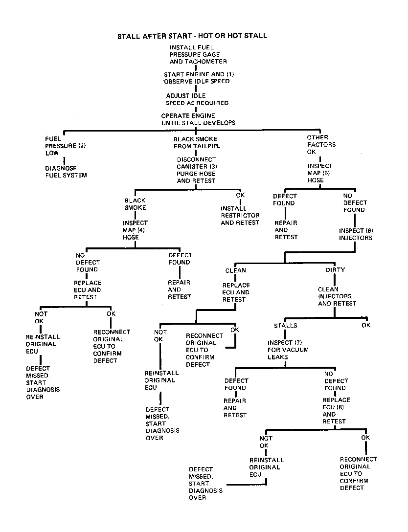
The diagnosis which follows covers a condition in which the engine stalls immediately, or as a driveaway is attempted with a hot to very hot engine. This is a different prob1cm from a condition in which the engine stalls while driving, such as in traffic or upon exiting a freeway.
1. A primary cause of this condition is low idle speed caused by an accumulation of deposits on the throttle valves and idle bypass passage. The idle speed should be set to 650 RPM, (600 RPM on 1975-1976 C and E)before any further diagnosis.
2. Normal fuel pressure is shown in Fig. 1. Low pressure is most easily diagnosed as described on Pages 44 thru 49. Fuel pressure which is low or was normal when the engine is started, but falls off as the stall develops, can be either an electrical or a fuel system problem. To eliminate the electrical aspects, repeat the stall with the Analyzer 5-25400 in step 20 (monitor) and observe the speed sensor, fuel pump, group I and 2, and ignition ON lights. Proper operation of the indicator lamps is as follows:
a. Trigger lights - these lamps indicate the connection made by each set of speed sensor contacts. The lights should blink alternately ON and OFF with equal intensity and with a constant rhythm. A lamp OFF, double blink, or a bright or weak blink indicates a speed sensor malfunction.If all lights operate normally as the stall develops, diagnose the fuel system as described on Pages thru - If no defect is found, replace the ECU and retest.
3. Black smoke from the tailpipe is obviously an indication of an excessively rich mixture. On 1976 Sevilles, remove the evaporative canister purge hose from the canister as the stall develops. If the stall is prevented and the idle smoothes out, an excessive amount of purging was taking place. The purge rate can be reduced by fabricating and installing a .0625 restrictor in the hose as shown in Fig. 4.
4. A leak in the MAP hose will alter the signal received by the ECU and may be severe enough to cause stall. To check the MAP hose, disconnect the hose at the throttle body and connect a hand vacuum pump such as 5-23738 to the hose. Develop a vacuum of 15” in the hose and check for leak down.
The MAP hose should also be inspected for kinks or restrictions at the throttle body, ECU and in the harness where the nylon line passes the exhaust manifold. If no defects have been found at this point, a new ECU should be installed on a trial basis.
A damaged hose can be replaced without replacing the entire line by splicing in a section of hose which conforms to GM Spec. 6107M.
5. A leak in the MAP hose will alter the signal received by the ECU and may be severe enough to cause stall. To check the MAP hose, disconnect the hose at the throttle body and connect a hand vacuum pump such as J-23738 to the hose. Develop a vacuum of IS” in the hose and check for leak down.
The MAP hose should also be inspected for kinks or restrictions at the throttle body, ECU and in the harness where the nylon line passes the exhaust manifold.
A damaged hose can be repaired without replacing the entire line by splicing in a section of hose which conforms to GM Spec. 6107M.
6. Injectors can become dirty enough to cause a lean stall, and the only method of determining this is through a visual inspection. Fig. 5 shows some examples of dirty injector tips. If inspection does not reveal dirty injectors, a new ECU should be installed on a trial basis.
However, if dirty injectors are discovered, the following cleaning procedure is recommended:
a. Remove plastic cap from around injector tip with flat bladed pliers by simultaneously pulling and twisting. (Only moderate gripping force necessary.)7. A vacuum leak at some points of the system may be severe enough to cause a lean stall condition. Look for leaks by squirting oil or listening for leaks at the following locations:
a. Throttle body to intake manifold.NOTE: A visual inspection can sometimes be used for this purpose.
Proper vacuum hose routing is shown in Figs. 12 thru 17.
NOTE: A porous intake manifold can also cause this condition.
8. If no defects have been found at this point, a new ECU should be installed on a trial basis.
No start |
Back to the top |
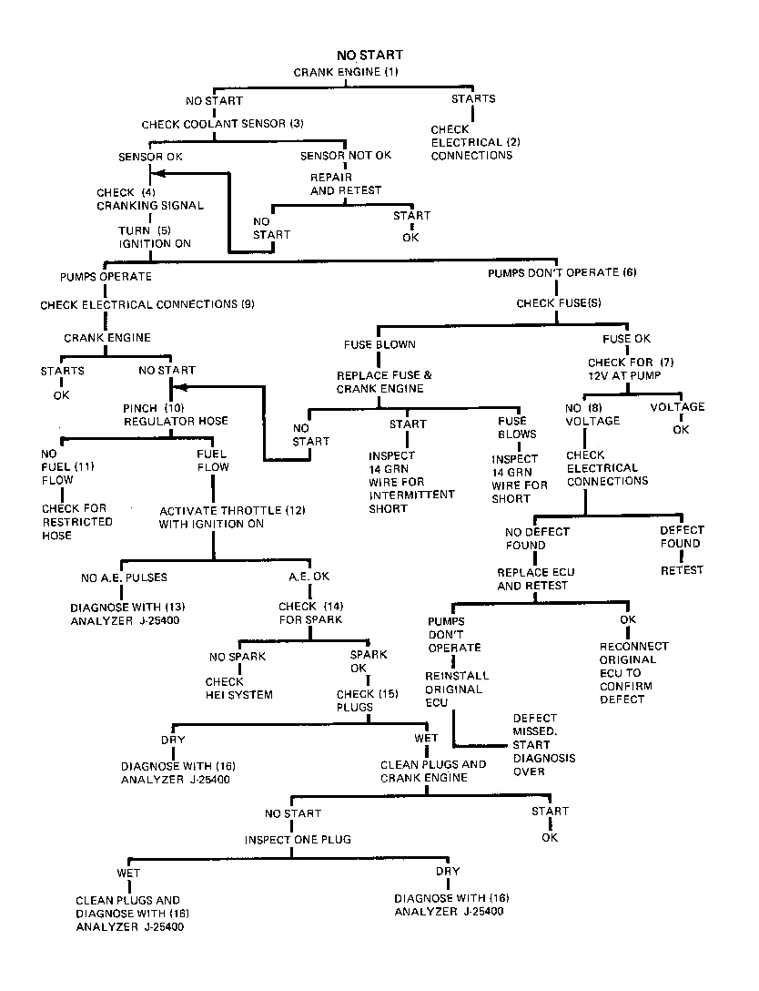
1. The first step of any diagnosis should be to confirm that the complaint condition does exist and to be sure that cranking speed is normal.
2. If the engine starts at this time but did not previously (owner complained), an intermittent electrical contact is indicated. Check all wires in the following connectors for tight, clean connections:
a. Fusible link wire at generator (circuit 801), and connectors in circuits 827 and 828.3. During cold operation the coolant sensor signal (low resistance) is used by the ECU to provide a richer pulse width. The resistance of the sensor can be determined with Analyzer 1-25400 in step 10, or can be determined with a VOM (volt-ohm meter) at the connector. A defective sensor is indicated if the resistance value does not compare with the value shown in Fig. 3.
If the sensor checks OK, it is still necessary to insure that the resistance signal is being delivered to the ECU. This can be accomplished with Analyzer 3-25400 or by probing terminals “D” and “G” of the red 9 way connector with the VOM. This value should be the same as that measured at the sensor.
4. Circuit 804 is a 12 purple wire from the starter solenoid to terminal “B” of the black 7 way connector which provides a signal that the engine is being cranked. The ECU uses this signal to switch to a wider pulse width for starting enrichment. If this signal is not received, the normal pulse width may be too short to start a cold engine. Probe terminal “B” of the black connector with a test light or VOM for the existence of this signal during crank.
5. The first diagnostic step in the chart will test the fuel pumps and circuit for proper operation. With the ignition switch ON, the pumps should run for one second and then stop. As the ignition is turned ON, listen for this one second pump operation.
6. Inoperative fuel pumps indicate a fuel system problem. Check the fuel pump fuse which is either in-line in the 14 dark geen wire or the 20 amp EM fuse in the fuse block. Also check the 20 amp “Gages-Trans” fuse on 77 C-Cars.
7. If fuse is OK but pumps fail to operate, check for voltage at the feed terminal of the chassis pump with a test light during the I second ignition on period. The ground connections for the fuel pumps should also be verified at this time. Refer to Figs. 18 through 22.
8. No voltage at the pumps is the result of no ECU output or an open iii the wiring. Check for voltage at terminal “C” of the blue 10 way connector(connectors still attached) as the ignition switch is cycled. A one second voltage here but not at the pumps isolates the open to the wiring between the ECU and the pumps. Refer to Figs. 18 through 22 for connector locations.
No voltage at terminal “C” indicates an ECU or ECU feed wire problem. Probe terminal “F” of the blue 10 way connector for voltage (connectors still attached). No voltage here isolates the open to the 16 brown wire and fusible link. However, voltage to the ECU (pin “F”) but not out (pin “C”) indicates an ECU malfunction or a lack of ignition feed to the ECU. Check terminal “F” of the black connector for voltage with ignition switch ON.
9. If the pumps operate, the possibility of an intermittent problem exists which must be eliminated before further diagnosis. Check the following connections:
a. Fusible link at generator10. If pumps do operate, a quick check can be performed to determine if fuel is actually being pumped through the system. With the aid of a helper, feel the fuel pressure regulator or return hose as the ignition switch is cycled (turned ON—OFF—ON—OFF). A “buzz” or vibration should be felt caused by fuel flowing through the regulator.
11. No fuel flow can be caused by any of the following conditions:
a. Restricted delivery line12. A check of the acceleration enrichment circuit verifies that the ECU is able to activate the injectors. To quickly check this circuit, turn the ignition switch ON and slowly activate the throttle from closed to wide open. The injectors should “click” each time an AE pulse is generated.
13. No AE pulses indicate a malfunction in either the ECU, its input signals or the output wiring. Test all of these signals with analyzer 1-25400.
14. Previous tests have confirmed proper operation of the fuel system (enough to start the car). To check for spark disconnect a spark plug wire and connect a spark testing tool (such as AC ST12S) to the wire and crank the engine. No spark indicates an HEI system problem which should be diagnosed as described in the appropriate year shop manual.
15. The balance of the diagnosis chart involves diagnosing malfunctions which are best found with analyzer 3-25400 after the spark plugs are confirmed as being in satisfactory condition. The plugs should be closely examined for cracked insulators and porcelain as well as fouled conditions.
16. In this situation, a malfunction in either the ECU, its input signals or the output wiring is indicated. Test all of these signals with analyzer J-25400.
Hard start - Cold |
Back to the top |
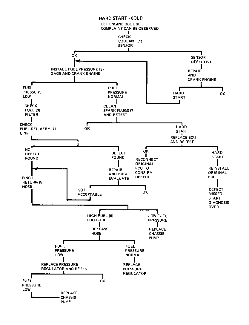
This condition is defined as an unusually long cranking period which eventually results in a driveable car. Diagnosis assumes that the cranking speed is normal.
1. During cold operation the coolant sensor signal (low resistance) is used by the ECU to provide a richer pulse width. The resistance of the sensor can be determined with Analyzer J-25400 in step 10, or can be determined with a VOM (volt-ohm meter). A defective sensor is indicated if the resistance value does not compare with the values shown in Fig. 3.
2. Low fuel pressure can cause hard starting since the required quantity of fuel is not delivered during the injector open time. Normal fuel pressure is shown in Fig. 1.
3. Low fuel pressure is an indication of a fuel supply problem. A collapsed or restricted fuel filter could be the cause. Inspect the filter for this condition.
4. Another source of supply restriction could be a kinked or damaged fuel delivery line. Inspect the full length of this line.
5. Since diagnosis this far has failed to find a reason why the fuel pressure is low, begin to suspect that the pump or the regulator may be the problem. With the engine at idle, pinch off the fuel return hose. This action is how the regulator raises the rail pressure, If the pressure does not increase to at least 46 PSIG, a defective chassis pump is indicated.
6. High fuel pressure with the return line pinched indicates that the chassis pump is capable of creating the increased pressures, but the regulator is unable to provide a restriction and is allowing the pressure to drain back to the tank. This indicates that regulator replacement is required.
NOTE: If pressure returns to normal when hose Is released, this indicates the foreign material that was holding the regulator off its seat has temporarily been cleaned off. If this material is too big to pass into the return hose, it will remain in the regulator and could cause this problem to reoccur. Since there is no way of knowing the size, the regulator should be replaced regardless.
7. Defective spark plugs will obviously cause hard starting. Remove the plugs and inspect especially for cracks in the porcelain insulation and condition of the electrode as well as fouling.
NOTE: Cracked insulators will not usually be shown on oscilliscope due to high voltages produced with HEI.
Hard start - Hot |
Back to the top |
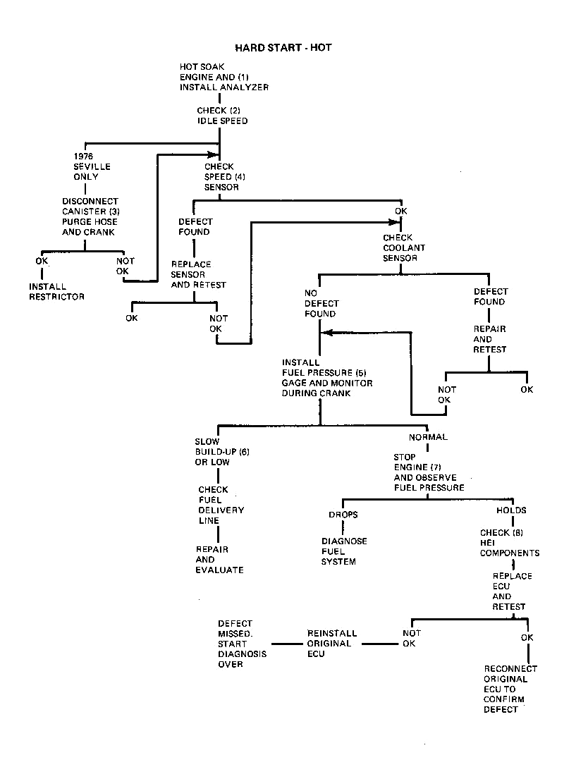
This condition is defined as an unusually long cranking period which eventually results in a driveable car. Diagnosis assumes that the cranking speed is normal.
1. Since a hot engine is required to duplicate this problem, the engine should be driven or idled until hot. High ambient temperatures are sometimes required for this condition to occur.
2. A primary cause of this condition is low idle speed caused by an accumulation of dirt on the throttle valves and idle bypass passage. The idle speed should be set to 650 RPM (600 RPM on 1975-1976 C and E) before any further diagnosis.
3. On 1976 Sevilles, remove the evaporative canister purge hose from the canister and crank the engine. If starting is improved and the idle smoothes out, an excessive amount of purging was taking place. The purge rate can be reduced by fabricating and installing a .0625” restrictor in the hose as shown in Fig. 4.
4. Watch speed sensor operation on the Analyzer during cranking. The “trigger” lamps indicate the connection made by each set of speed sensor contacts. These lights should blink ON and OFF with equal intensity and with a constant rhythm. A lamp OFF, double blink or a bright or weak blink indicates a speed sensor malfunction.
5. Low fuel pressure can cause hard starting by reducing the amount of fuel injected during the injector open time.
6. Low fuel pressure indicates a restriction in the fuel delivery line. Inspect the entire length for kinks or damage.
7. Even with normal fuel pressure during cranking, an internal leak in the system may allow vapors to form in the fuel rails at high ambient temperatures. This condition will cause a long crank period as cool fuel must be pumped from the tank to replace the vapor when the engine is restarted.
With the engine off, the pressure in the rails should not drop more than 5 psi in 2 minutes. Pressure drop indicates a fuel system leak. Diagnose the fuel system as described on Pages 44 through 49.
8. An ignition deficiency can easily create hot start problems. The HE! system should be diagnosed as described in the appropriate year shop manual.
If the problem has not been solved at this point, a new ECU should be installed on a trial basis.
Stalls while driving - Immediate restart |
Back to the top |
STALLS WHILE DRIVING — IMMEDIATE RESTART (INTERMITTENT)
1. Intermittent problems are most easily diagnosed with Analyzer 1-25400 installed and operating in step 20 (monitor). In this position, the analyzer is merely in the circuit indicating the events through the lights and digital read-out as they occur. It is also helpful to be able to observe the fuel pressure during driving situations. This can be accomplished by connecting an A/C charging line to the pressure gage with a suitable adapter (such as Weatherhead #42x4 connector). A vacuum gage should be teed into the pressure regulator vacuum line. Route the hoses out of the engine compartment to a position where the gages can be read inside the car.
NOTE: This extra length of hose should be used for monitoring fuel pressure only. The short hose supplied with Analyzer J-25400 must be used for fuel system testing as the additional length will not provide accurate enough gage response.
2. Drive the car and watch the Analyzer’s indicator lights as the stall develops. Proper operation of the indicator lamps is as follows:
a. Trigger lights - these lamps indicate the connection made by each set of speed sensor contacts. The lights should blink alternately ON and OFF with equal intensity and with a constant rhythm. A lamp OFF, double blink, or a bright or weak blink indicates a speed sensor malfunction.3. It is important to remember that the trigger and group lights are related in that if the trigger gives an improper signal, the group lights will normally show an identical symptom. For instance, if the trigger does not dose one set of contacts, the ECU will not activate one group of injecton. This is a trigger malfunction and there is nothing wrong with the ECU. However, if the group lights indicate a malfunction with normal indications from the speed sensor, an ECU malfunction is indicated.
4. A marginal ignition switch adjustment can disconnect the ignition ON signal (circuit 828) from the ECU. Check this adjustment as described in the appropriate year shop manual.
5. Momentary fuel pressure loss is usually caused by a loose connection in the fuel pump circuit. Check the connections in circuits 827, 120 and 802 as well as the ground connections. Refer to Figs. 18 thai 22.
6. Poor electrical connections which can cause this condition are:
a. Ground wires at fenderwell or injector bracket.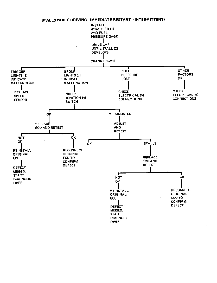
Stalls while driving - No immediate restart |
Back to the top |
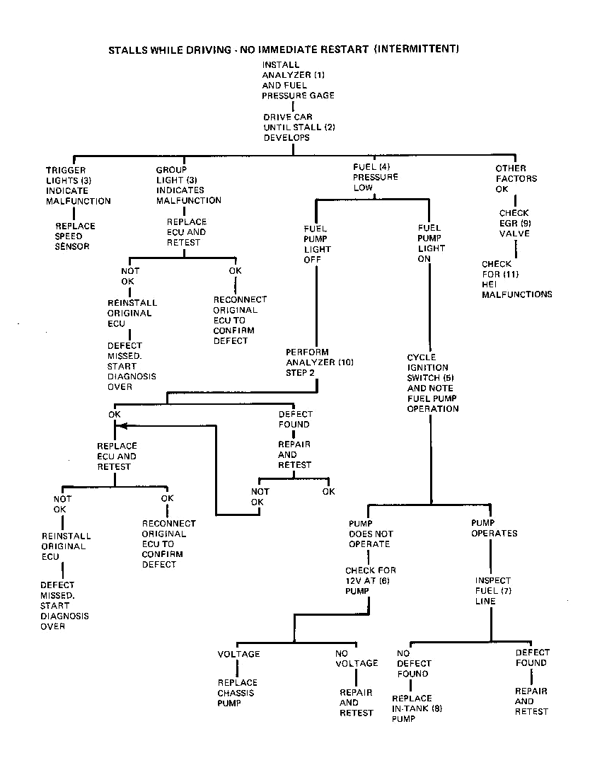
1. Intermittent problems are most easily diagnosed with Analyzer J-25400 installed and operating in step 20 (monitor). In this position, the analyzer is merely in the circuit indicating the events through the lights and digital read-out as they occur. It is also helpful to be able to observe the fuel pressure during driving situations. This can be accomplished by connecting an A/C charging line to the pressure gage with a suitable adapter (such as Weatherhead #42x4 connector). A vacuum gage should be teed into the pressure regulator vacuum hose. Route the hoses out of the engine compartment to a position where the gages can be read inside the car.
NOTE: This extra length of hose should be used for monitoring fuel pressure only. The short hose supplied with Analyzer J-25400 must be used for fuel system testing as the additional length will not provide accurate enough gage response.
2. Drive the car and watch the Analyzer’s indicator lights as the stall develops. Proper operation of the indicator lamps is as follows:
a. Trigger lights - these lamps indicate the connection made by each set of speed sensor contacts. The lights should blink alternately ON and OFF with equal intensity and with a constant rhythm. A lamp OFF, double blink, or a bright or weak blink indicates a speed sensor malfunction.3. It is important to remember that the trigger and group lights are related in that if the trigger gives an improper signal, the group lights will normally show an identical symptom. For instance, if the trigger does not close one set of contacts, the ECU will not pulse one group of injectors. This is a trigger malfunction and there is nothing wrong with the ECU. However, if the group lights indicate a malfunction with normal indications from the speed sensor, an ECU malfunction is indicated.
4. Normal fuel pressure is shown in Fig. 1.
5. The analyzer’s fuel pump light is only an indication that the ECU signal to activate the fuel pumps exists. To confirm that the pumps actually operate, cycle the ignition switch (ON—OFF—ON—OFF) and listen for fuel pump operation during the one second period.
6. Check for voltage at the chassis mounted fuel pump feed terminal (green wire) and check the ground connections. No voltage indicates an open in the 14 dark green wire between the ECU and the fuel pump. Refer to Figs. 18 thru 22.
7. If the pump operates but fuel pressure is low at the fuel rail, the possibility of a restricted fuel filter or supply line should be eliminated before further diagnosis. This is a visual check of the filter and line for kinks or damage.
8. A failure of the in-tank pump could stop fuel delivery to the chassis mounted pump and not show up during cold to moderate temperature operation. Since in-tank pump failure is difficult to diagnose, the pump should be replaced if its performance is suspected.
9. A sticking open EGR valve can dilute the mixture to a point where the idle becomes rough and the engine stalls. EGR during crank can dilute the fuel mixture and prevent starting
The signal which operates the EGR valve is a ported vacuum signal on all cars. Since this signal does not exist with the throttle valves closed, and is only produced as the throttle valves pass the EGR port in the throttle opening, it can be seen that there should be no EGR operation at idle.
To check for this condition, remove the EGR valve, block the passages in the intake manifold and crank the engine. The EGg vacuum hose can be inspected at this time for a signal at idle which should not exist. If car will start, clean or replace valve as required.
10. The analyzer’s fuel pump light indicates the existence of the fuel pump ON signal from the ECU. The fact that this light is OFF indicates that the ECU has shut it off or that an erroneous signal has been received which will cause the ECU to normally stop this signal. Step 2 of the analyzer procedure will check the input signals. If the circuit is good, an ECU replacement is indicated.
11. Since analysis has given no indication of an EFI failure, the ignition system is a likely suspect. Diagnose the HEI system as described in the appropriate model year Shop Manual.
Tip - In stumble |
Back to the top |
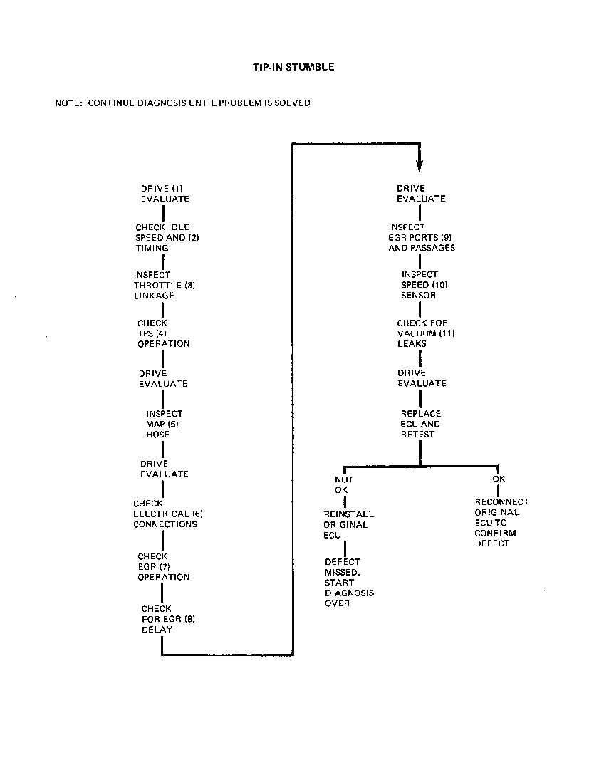
1. The first step in any diagnosis should be an evaluation of the problem. In the case if driveabiity problems, this is especially important, so that driveability improvements can be judged.
2. Low idle speed and improper ignition timing are two primary causes of this problem. These adjustments should be set to specification before any further diagnosis is attempted. If these adjustments were incorrect, a second drive-evaluation may be helpful.
3. A throttle linkage bind can cause the throttle to “hang-up”, which feels very much like a stumble. Inspect the rubbing surface on the accelerator pedal, the under hood linkage and the position of the floor mat (jammed up under the pedal or resting on top of pedal). Do not overlook the importance of the floor mat as this can keep the throttle from returning all the way, thus depriving the TPS of providing an OCT pulse.
4. Check the TPS for proper operation by rotating the throttle from closed to WOT with the ignition switch ON. The injectors should click 21 times (all clicks will be from one group of injectors). No additional clicks should be heard as throttle is closed.
NOTE: When WOT is reached, the EGR solenoid will click (when warm). Do not count this as an AE pulse.
Less than 21 clicks indicates a TPS adjustment is necessary. To adjust switch, proceed as follows:
a. Loosen two TPS mounting screws to permit rotation of switch.5. A restriction in the MAP line will alter the MAP signal to the ECU. The hose should be inspected for kinks or restrictions at the throttle body, ECU and in the harness where the nylon line passes the exhaust manifold. A damaged hose can be repaired without replacing the entire line by splicing in a section of hose which conforms to GM spec. 6107 M.
An alternate method of checking for a restricted line is to bypass the existing hose with a new hose (approximately the length of the existing hose) and drive the car. A significant improvement indicates a kinked or restricted hose.
6. Poor connections which are likely to cause this condition arc;
a. Injector ground at fenderwell or injector bracket.7. Any lean or momentary lean condition can cause a tip-in stumble. With EFI, no EGR creates a lean condition. When EGR is functioning praperly, a certain amount of inert exhaust gas is added to the air/fuel mixture in each cylinder. If there is no EGR operation, the space normally taken up by the exhaust gas is replaced by additional air, since the ECU has not been calibrated to provide additional fuel, and a lean condition results. A “quick check” of EGR system function should be performed as follows:
a. With engine running, operate throttle. Diaphragm should raise as throttle is opened.8. The signal which turns the EGR system on is a ported vacuum signal on all cars. Since this signal does not exist with the throttle valves closed, and is only produced as the throttle valves pass the EGR port in the throttle opening, it can be seen that this is a timed signal. A delay in this signal will cause EGR to be added at the wrong fl~. The most common reason for a delayed signal is a leak in the EGR vacuum hoses. Inspect these hoses and the backpressure transducer signal tube for leakage. Vacuum hose connections are shown in Figs. 12 thru 17.
The amount of EGR delivered to the intake manifold is also important to good engine driveability. The quantity of EGR is proportional to the size of the opening in the orifice-gasket located between the transducer and the manifold, Fig. 6. The size of the orifice can be determined by the configuration of the notches as shown in Fig. 7. This identification can be made without removing the valve and should be done at this time.
9. As described above, the timing and quantity of EGR gases is critical to good driveability. If the “quick check” indicates a blockage, the following procedure should be performed. In addition, a partial blockage condition should be investigated after the “correct parts” determination has been made in step 8. Remove the throttle body and inspect the following:
a. EGR signal port in throttle body (this is the rectangular port in the right hand throttle bore which is connected to the outer nipple on the right hand side of the throttle body adapter). Inspect this port for any deposit build-up and clean as necessary.10. The two speed sensor switches are closed by magnets rotating on the distributor shaft. The closing of the switches provides signals which are used by the ECU to determine which group of injectors should be energized. If improper service of the distributor has resulted in mispositioning of the magnets, a stumbling condition can result. Remove the distributor and compare the magnet orientation to Figs. 8 and 9.
Improper service can also result in the speed sensor assembly being installed upside down. Proper installation of the sensor results in the wiring coming out of the top of the sensor under the distributor housing with part number visible on the outside.
11. A vacuum leak at some points of the system may be severe enough to cause a stumble. Look for leaks by squirting oil or listening for leaks at the following locations:
a. Throttle body to intake manifold.NOTE: A visual inspection can sometimes be used for this purpose.
Proper vacuum hose routing is shown in Figs. 12 thru 17.
NOTE: A porous intake manifold can also cause this condition.
A small vacuum leak near a particular cylinder will cause all of the air from the leak to be drawn into the closest cylinder. This will usually show up during cylinder balance testing as a weak cylinder. This indication should be a hint to look for vacuum leaks near that cylinder.
Surge (lean operation) |
Back to the top |
1. The first step in any diagnosis should be an evaluation of the problem. In the case of driveability problems, this is especially important, so that driveabiity improvements can be judged.
2. Poor connections which are likely to cause this condition are:
a. Injector ground at fenderwell or injector bracket.3. Any lean condition can cause surge. With EFI, no EGR creates a lean condition. When EGR is functioning properly, a certain amount of inert exhaust gas is added to the air/fuel mixture in each cylinder. If there is no EGR operation, the space normally taken up by the exhaust gas is replaced by additional air, since the ECU has not been calibrated to provide additional fuel and a lean condition results. A “quick check” of EGR system function should be performed as follows:
a. With engine running, operate throttle. Diaphragm should raise as throttle is opened.The signal which turns the EGR system on is a ported vacuum signal on all cars. Since this signal does not exist with the throttle valves closed, and is only produced as the throttle valves pass the EGR port in the throttle opening, it can be seen that this is a timed signal. A delay in this signal will cause EGR to be added at the wrong time. The most common reason for a delayed signal is a leak in the EGR vacuum hoses. Inspect these hoses and the back-pressure transducer signal tube for leakage. Vacuum hose connections are shown in Figs. 12 thru 17.
The amount of EGR delivered to the intake manifold is also important to good engine driveability. The quantity of EGR is proportional to the size of the opening in the orifice-gasket located between the transducer and the manifold, Fig. 6. The size of the orifice can be determined by the configuration of the notches as shown in Fig. 7. This identification can be made without removing the valve and should be done at this time. Remove the throttle body and inspect the following:
a. EGR signal port in throttle body (this is the rectangular port in the right hand throttle bore which is connected to the outer nipple on the right hand side of the throttle body adapter). Inspect this port for any deposit build-up and clean as necessary.4. Install fuel pressure and vacuum gages and observe the pressure during the surge condition. This can be accomplished by connecting an A/C charging line to the pressure gage with a suitable adapter (such as Weatherhead #42 x 4 connector). The vacuum gage should be teed into the pressure regulator vacuum line. Route the hose out of the engine compartment to a position where the gages can be read inside the car.
NOTE: This extra length of hose should be used for monitoring fuel pressure only. The short hose supplied
with analyzer J-25400 must be used for fuel system testing as the additional length will not provide accurate enough gage response.
5. Low fuel pressure under load is an indication of a fuel supply problem. A collapsed or restricted fuel filter could be the cause. Inspect the filter for this condition.
6. Another source of supply restriction could be a kinked or damaged fuel delivery line. Inspect the full length of this line.
7. Since diagnosis this far has failed to find a reason why the fuel pressure is low, begin to suspect that the pump or the regulator may be the problem. With the engine at idle, pinch off the fuel return hose. This action is how the regulator raises the rail pressure. If the pressure does not increase to at least 46PSIG, a defective chassis pump is indicated.
8. High fuel pressure with the return line pinched indicates that the chassis pump is capable of creating the increased pressures, but the regulator is unable to provide a restriction and is allowing the pressure to drain back to the tank. This indicates that regulator replacement is required.
NOTE: If pressure returns to normal when hose is released, this indicates the foreign material that was holding the regulator off its seat has temporarily been cleaned off. If this material is too big to pass into the return hose, it will remain in the regulator and could cause this problem to reoccur. Since there is no way of knowing the size, the regulator should be replaced regardless.
9. Injectors can become dirty enough to cause a lean surge condition. The only method of determining their condition is through a visual inspection. Fig. 5 shows some examples of dirty injector tips. If inspection does not reveal dirty injectors, a new ECU should be installed on a trial basis.
However, if dirty injectors are discovered, the following cleaning procedure is recommended:
a. Remove plastic cap from around injector tip with flat bladed pliers by simultaneously pulling and twisting. (Only moderate gripping force necessary.)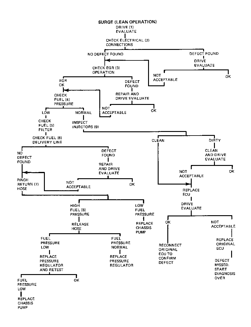
Rich operation - Black smoke from the tailpipe |
Back to the top |
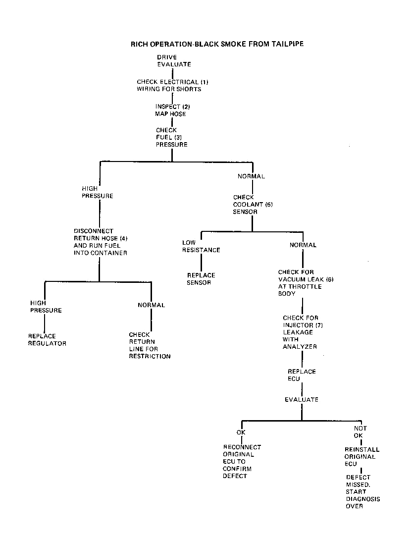
1. Short circuits in the following wires can cause this condition:
a. Coolant Sensor2. A leak in the MAP hose will cause this condition as it will alter the signal received by the ECU. To check the MAP hose, disconnect the hose at the throttle body and connect a hand vacuum pump such as 1-23738 to the hose. Develop a vacuum of 15” in the hose and check for leak down. A damaged hose can be replaced without replacing the entire line by splicing in a section of hose which conforms to GM spec. 6107 M.
Also check the vacuum hose at the fuel pressure regulator as a leak in this line will alter the MAP signal as well as increase the fuel pressure.
3. Start engine and run for at least 1 minute. High fuel pressure will cause rich operation as a greater quantity of fuel will be injected with each injector opening. Normal fuel pressure is shown in Fig. I.
4. If the car has high fuel pressure, this fact proves the capabilities of the chassis pump and isolates the problem to either the regulator or return hose. To check these components, remove the fuel return hose from the pressure regulator and run a line between the regulator and a suitable container. Run the engine and observe the fuel pressure. If the pressure is normal, the restriction (return hose) has been eliminated. However, if the pressure is still high, a noncontrolling regulator is indicated.
5. The coolant sensor provides low resistance when it is cold. If the sensor is shorted, this low resistance will continue to be supplied to the ECU which will continue to provide a long (rich) pulse width. The resistance of the sensor can be determined with analyzer 1-25400 in step 10, or can be determined with a VOM (volt-ohm meter) at the connector. A defective sensor is indicated if the resistance value does not compare with the values shown in Fig. 3.
If the sensor checks OK, it is still necessary to insure that the resistance signal is being delivered to the ECU. This can be accomplished with analyzer 1-25400 or by probing terminals “D” and “G” of the red 9 way connector with the VOM. This value should be the same as that measured at the sensor.
6. Vacuum leaks at the throttle body will alter the MAP signal the same as a leaking hose. Inspect the throttle body for this condition.
7. An injector which is sticking open will cause a rich condition even though all other components are operating normally. This condition can be analyzed as described on Pages 44 through 49
If no defects have been found at this point a new ECU should be installed on a trial basis.
Hesitation |
Back to the top |
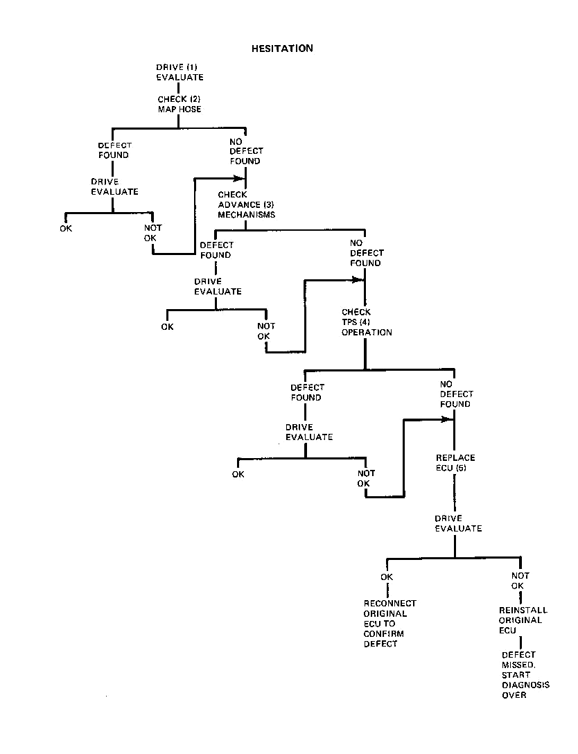
1. The first step in any driveability diagnosis should be an evaluation of the severity of the complaint.
2. A restricted MAP hose will alter the signal to the ECU.
The hose should be inspected for kinks or restrictions at the throttle body, ECU and in the harness where the nylon line passes the exhaust manifold. Repairs to the existing line can be performed without replacing the entire harness by splicing in a section of hose which conforms to GM spec. 6107 M. An alternate method of checking for a restricted line is to bypass the existing hose with a new hose (close to the length of the existing hose) and drive the car. A significant improvement indicates a kinked or restricted hose.
An alternate method of checking for a restricted line is to bypass the existing hose with a new hose (close to the length of the existing hose) and drive the car. A significant improvement indicates a kinked or restricted hose.
3. Proper operation of the centrifugal and vacuum advance mechanisms is as important as proper initial timing setting to good driveability. The following test is designed to prove that these mechanisms are functioning somewhere near normally.
Chart 1 on Page 50 lists points at which the centrifugal advance mechanism can be tested. The specifications are listed in engine RPM and engine-crankshaft degrees. This test is most easily performed with a tachometer and a timing light with a timing advance meter. The centrifugal advance should be examined with the vacuum hose(s) to the vacuum advance unit disconnected and plugged.
To check centrifugal advance, proceed as follows:
a. Run engine at idle and note timing mark on pulley. Should read initial setting (as specified on underhood label). Advance meter will read zero.To check vacuum advance, proceed as follows:
a. Run engine at idle with vacuum advance hose(s) disconnected and plugged.4. Check the TPS for proper operation by rotating the throttle from closed to WOT with the ignition switch ON. The injectors should click 21 times (all clicks will be from one group of injectors). No additional clicks should be heard as throttle is closed.
NOTE: When WOT is reached, the EGR solenoid will click (when warm). Do not count this as an AE pulse.
Less than 21 clicks indicates a TPS adjustment is necessary. To adjust switch, proceed as follows:
a. Loosen two TPS mounting screws to permit rotation of switch.5. If no defects have been found at this point, the ECU should be replaced on a trial basis.
Rough idle |
Back to the top |
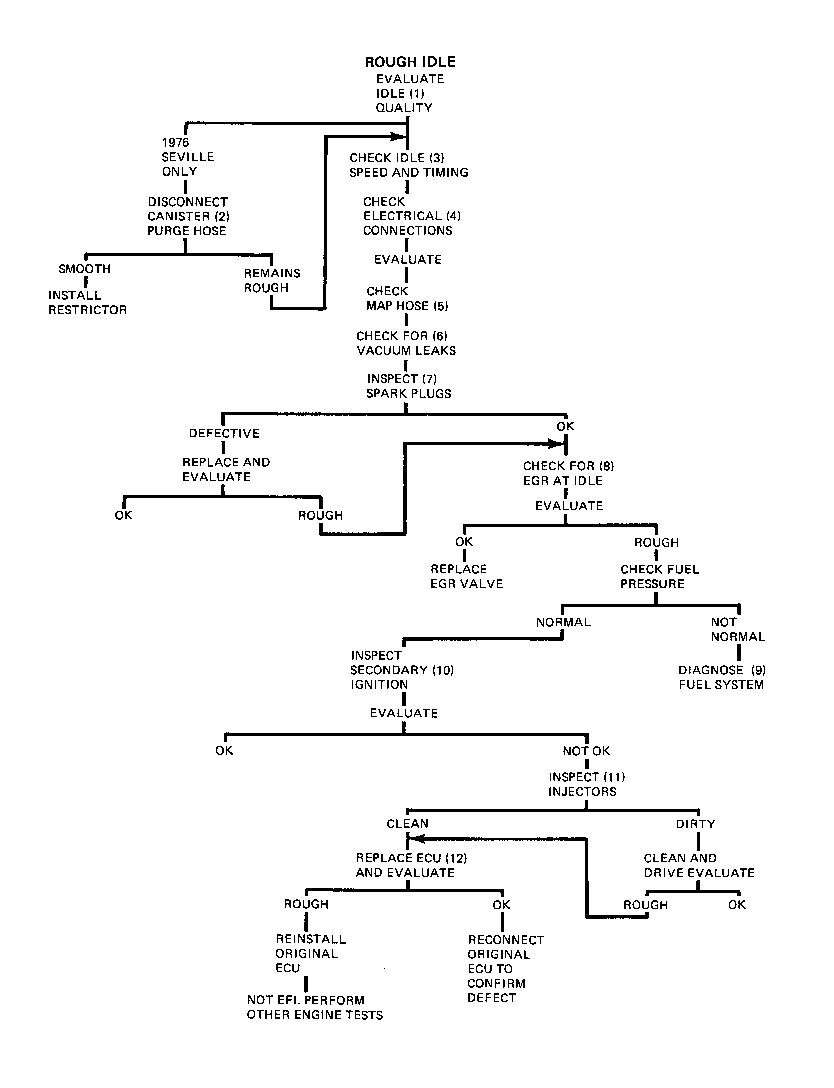
1. The first step in any diagnosis should be an evaluation of the severity of the complaint. For rough idle evaluation be sure to observe the idle condition with the engine in DRIVE as the idle in PARK may be entirely different.
2. On 1976 Sevilles, remove the evaporative canister purge hose from the canister and start the engine. If the idle smoothes out, an excessive amount of purging was taking place. The purge rate can be reduced by fabricating and installing a .0625” restrictor in the hose as shown in Fig. 4.
3. Proper idle speed and ignition timing probably have more influence on idle quality than any other factors. Set idle speed to 650 RPM (600 RPM on 1975-1976 C and E) and ignition timing to the specification on the underhood label before further diagnosis is attempted.
4. Poor electrical connections which could cause rough idle are:
a. Injectors5. A leak in the MAP hose will cause rough idle since the MAP signal is altered. To check the MAP hose, disconnect the hose at the throttle body and connect a hand vacuum pump such as J-23738 to the hose. Develop a vacuum of 15” in the hose and check for leak down. A damaged hose can be replaced without replacing the entire line by splicing in a section of hose which conforms to GM spec. 6107 M.
6. A vacuum leak at any point of the system may be severe enough to cause a lean condition. Look for leaks by squirting oil or listening for leaks at the following locations:
a. Throttle body to intake manifold.NOTE: A visual inspection can sometimes be used for this purpose.
Proper vacuum hose routing is shown in Figs. 12 thru 17.
NOTE: A porous intake manifold can also cause this condition.
7. Defective spark plugs will obviously cause rough idle. Remove the plugs and inspect, especially for cracks in the porcelain insulation and condition of the electrode as well as fouled conditions.
NOTE: Cracked insulators will not usually be shown on oscilliscope due to high voltages produced with HEI.
8. The signal which operates the EGR valve is a ported vacuum signal on all cars. Since this signal does not exist with the throttle valves closed, and is only produced as the throttle valves pass the EGR port in the throttle opening, it can be seen that there should be no ECR operation at idle. EGR at idle will obviously cause a roughness.
To check for this condition, remove the EGR valve and block the passages in the intake manifold. Idle quality should be evaluated in this condition. The EGR vacuum hose can be inspected at this time for a signal at idle which should not exist. If idle is better, clean or replace valve as required.
9. High or low fuel pressure can cause rough idle caused by lean or rich mixtures respectively. Abnormal pressures are best diagnosed as described on Pages 44 through49if this problem is discovered.
10. The plug wires (especially numbers S and? on Seville), cap and rotor should be inspected for crossfiring or abnormal conditions. This analysis can be performed on an oscilliscope by a trained observer.
11. Injectors can become dirty enough to cause rough idle. The only method of determining their condition is through a visual inspection. Fig. 5 shows some examples of dirty injector tips.
In addition to dirty injectors, damaged tips such as shown in Fig. 10 can alter the flow characteristics of the injector to cause rough idle. Damaged injectors must be replaced.
If dirty injectors are discovered, the following cleaning procedure is recommended:
a. Remove plastic cap from around injector tip with flat bladed pliers by simultaneously puffing and twisting. (Only moderate gripping force necessary.)12. If the idle quality has not been improved to an acceptable level at this point, a new ECU should be installed on a trial basis.
Idle speed change |
Back to the top |
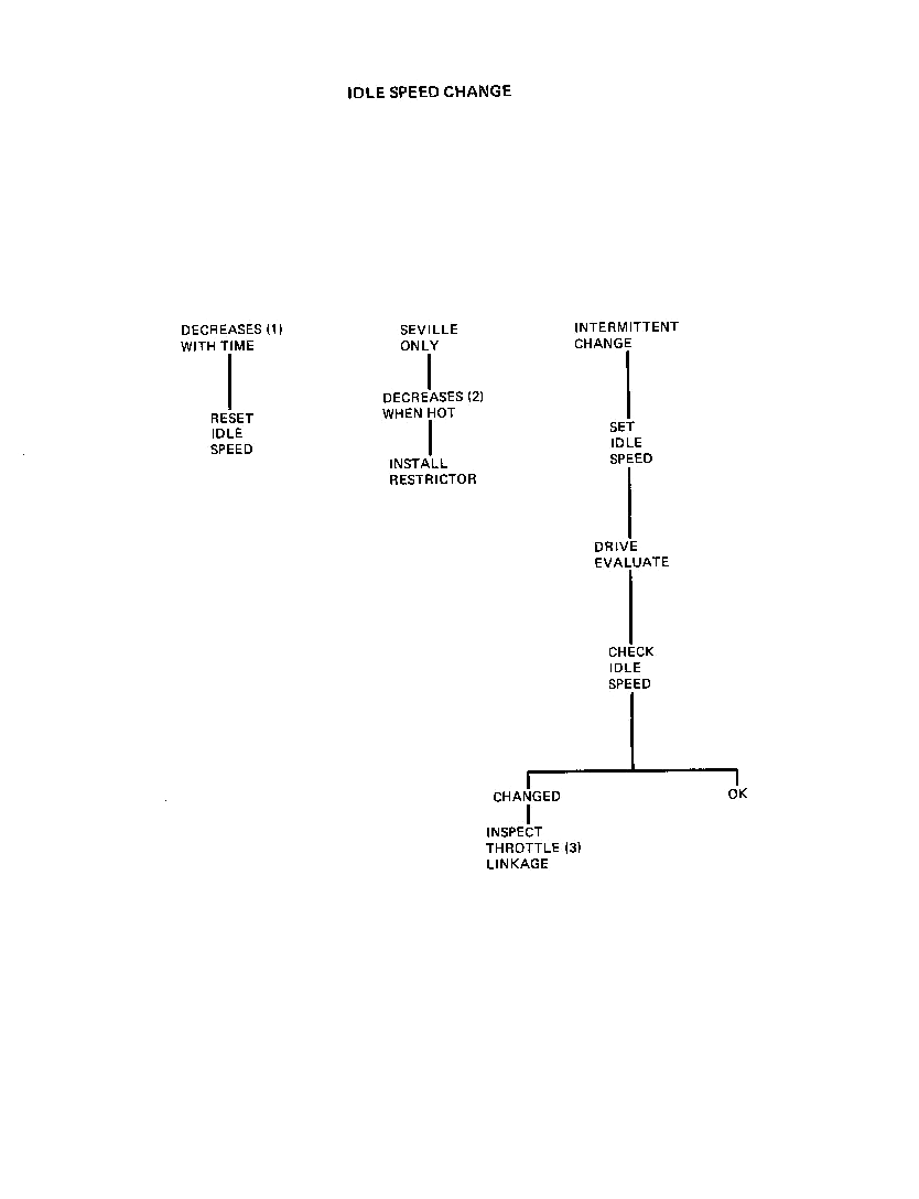
1. Idle speed which changes (lower) over a period of time is usually due to the build-up of deposits along the throttle blades and the idle bypass passage. Since fuel is not drawn through the throttle body, the deposits are not cleaned off.
Readjusting the idle speed to 650 RPM (600 RPM on 1975-I 976 C and E) will restore normal EFI operation.
2. In high ambient temperatures, the EEC vapor canister is required to store unusually large amounts of fuel vapor from the tank. As soon as the engine is started, this vapor is drawn into the throttle body to be burned in the engine,
3. When this fuel vapor is added to the normal fuel provided by the injectors, an overly rich condition can result causing low idle speed. This condition can be rectified by fabricating and installing a .0625” restrictor in the hose as shown in Fig. 4.
4. An idle speed which changes for no apparent reason can usually be traced to a binding linkage. With the ignition ON, open throttle with accelerator pedal and slowly return to idle. Check to make sure that throttle lever rests on idle stop screw at throttle body. If not, check for bind in linkage and TPS adjustment. Another cause for this condition may be the floor mat interfering with the accelerator pedal. Do not overlook this possibility as it can also cause other problems.
Misfire on light acceleration |
Back to the top |
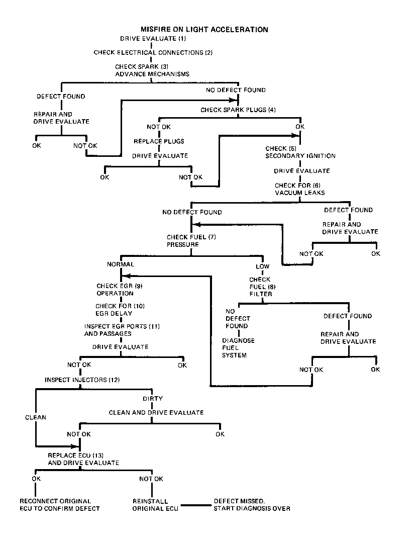
The condition discussed in this diagnosis is a miss or series of light hesitations which occur under light acceleration. A moderate acceleration will clear up this condition.
1. The first step in any diagnosis should be an evaluation of the problem. In the case of driveability problems, this is especially important so that driveability improvements can be judged.
2. Poor electrical connections which can cause this condition are:
a. Injectors3. Proper operation of the centrifugal and vacuum advance mechanisms is as important to good driveability as proper initial timing setting. The following test is designed to prove that these mechanisms are functioning somewhere near normally.
Chart 1 on Page 50 lists points at which the centrifugal advance mechanism can be tested. The specifications are listed in engine RPM and engine-crankshaft degrees. This test is most easily performed with a tachometer and a timing light with a timing advance meter. The centrifugal advance should be examined with the vacuum hose(s) to the vacuum advance unit disconnected and plugged.
To check centrifugal advance, proceed as follows:
a. Run engine at idle and note timing mark on pulley. Should read initial setting (as specified on underhood label). Advance meter will read zero.To check vacuum advance, proceed as follows:
a. Run engine at idle with vacuum advance hose(s) disconnected and plugged.4. Defective spark plugs will obviously cause a misfire. Remove the plugs and inspect especially for cracks in the porcelain insulation and condition of the electrode as well as fouling.
NOTE: Cracked insulators will not usually be shown on oscilliscope due to high voltages produced with HEI.
5. The plug wires (especially numbers S and 7 on Seville), cap and rotor should be inspected for crossfiring or abnormal conditions. This analysis can be performed on an oscilloscope by a trained observer.
6. Vacuum leaks at the following connections can contribute to misfire:
a. Throttle body to intake manifold7. Low fuel pressure can cause a misfire by creating a lean condition.
Install fuel pressure and vacuum gages and observe the pressure during the misfire condition. This can be accomplished by connecting an A/C charging line to the pressure gage with a suitable adapter (such as Weatherhead #42x4 connector). The vacuum gage should be teed into the pressure regulator vacuum line. Route the hoses out of the engine compartment to a position where the gages can be read inside the car.
NOTE: This extra length of hose should be used for monitoring fuel pressure only. The short hose supplied with analyzer J-25400 must be used for fuel system testing as the additional length will not provide accurate enough gage response.
8. Low fuel pressure under load is an indication of a fuel supply problem. A collapsed or restricted fuel filter could be the cause. Inspect the filter for this condition. If filter is not obstructed or collapsed, continue fuel system diagnosis as described on Pages 44 through 49.
9. Any lean or momentary lean condition can cause a misfire. With EFI, no EGR creates a lean condition. When EGR is functioning properly, a certain amount of inert exhaust gas is added to the air/fuel mixture in each cylinder. If there is no EGR operation, the space normally taken up by the exhaust gas is replaced by additional air. Since the ECU has not been calibrated to provide additional fuel, and a lean condition results. A “quick check” of EGR system function should be performed as follows:
a. With engine running, operate throttle. Diaphragm should raise as throttle is opened.10. The signal which turns the EGR system on is a ported vacuum signal on all cars. Since this signal does not exist with the throttle valves closed, and is only produced as the throttle valves pass the EGR port in the throttle opening, it can be seen that this is a timed signal. A delay in this signal will cause EGR to be added at the wrong time. The most common reason for a delayed signal is a leak in the vacuum hoses. Inspect these hoses and the backpressure transducer signal tube for leakage. Vacuum hose connections are shown in Figs. 12 thru 17.
The amount of EGR delivered to the intake manifold is also important to good engine driveabiity. The quantity of EGR is proportional to the size of the opening in the orifice-gasket located between the transducer and the manifold, Fig. 6. The size of the orifice can be determined by the configuration of the notches as shown in Fig. 7. This identification can be made without removing the valve and should be done at this time.
11. As described above, the timing and quantity of EGR gases is critical to good driveability. If the “quick check” indicates a blockage, the following procedure should be performed. In addition, a partial blockage condition should be investigated after the “correct parts” determination has been made in step 10. Remove the throttle body and inspect the following:
a. EGR signal port in throttle body (this is the rectangular port in the right hand throttle bore which is connected to the outer nipple on the right hand side of the throttle body adapter). Inspect this port for any dirt build-up and clean as necessary.12. Injectors can become dirty enough to cause a misfire. The only method of determining their condition is through a visual inspection. Fig. 5 shows some examples of dirty injector tips, If inspection does not reveal dirty injectors, a new ECU should be installed on a trial basis.
In addition to dirty injectors, damaged tips such as shown in Fig. 10 can alter the flow characteristics of the injector to cause a misfire. Damaged injectors must be replaced.
However, if dirty injectors are discovered, the following cleaning procedure is recommended:
a. Remove plastic cap from around injector tip with flat bladed pliers by simultaneously pulling and twisting. (Only moderate gripping force necessary).13. If the misfire has not been eliminated at this point, a new ECU should be installed on a trial basis.
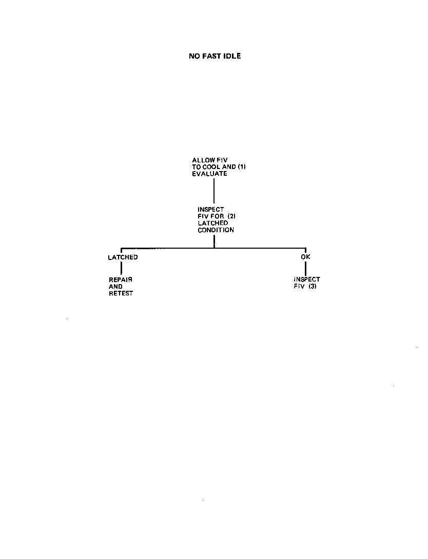
No fast idle |
Back to the top |
1. To evaluate the FIV, proceed as follows:
a. Park the car in a 70-80°F. ambient temperature, shut engine off and remove air cleaner assembly.2. A “latched” FIV is a condition where the retainer clip becomes “latched” below the seat, thus holding the valve in its closed position, Fig. 2. To check for this condition, remove the valve and visually inspect.
NOTE: The white substance found on the bottom of the heater is a heat transfer compound and does not indicate a heater failure.
A latched FIV can occur either as a result of a heating element malfunction or removal of the valve.
3. A fast idle valve which sticks or binds in the orifice can cause this condition. Inspect these parts for evidence of this situation.
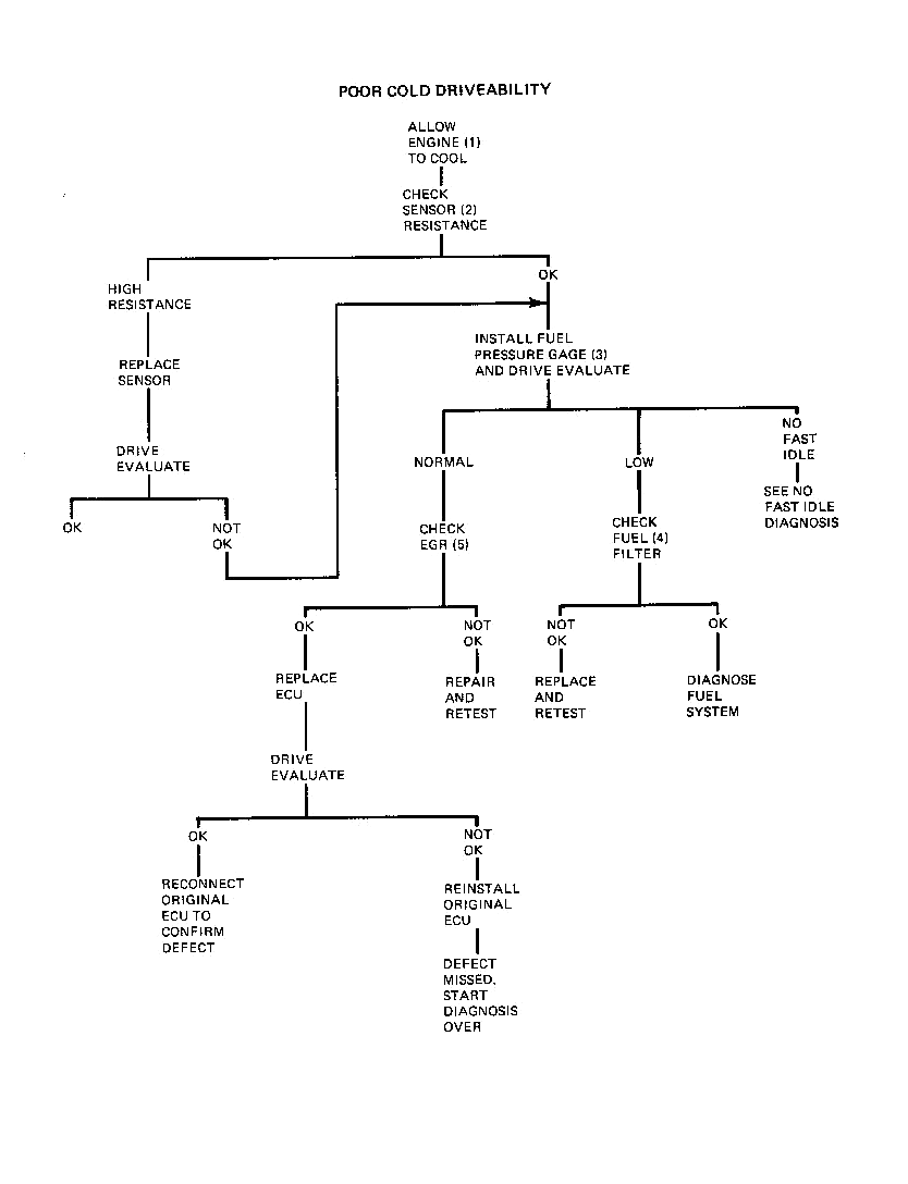
Poor cold driveability |
Back to the top |
1. The first step in any diagnosis should be to confirm that the complaint condition does exist and to observe its severity. Obviously a cold complaint can only be observed when the engine is cold.
2. During cold operation the coolant and air sensor’s signal (low resistance) is used by the ECU to provide a richer pulse width. The resistance of the sensors can be determined with Analyzer J-25400 in steps 10 and 11, or can be determined with a VOM (volt.ohm meter). A defective sensor is indicated if either resistance value does not compare with the value shown in Fig. 3. If the sensors check OK, it is still necessary to insure that the resistance signal is being delivered to the ECU. This can be accomplished with analyzer or by probing terminals “0” and “G” of the red 9 way connector for the coolant sensor, and terminals “C” and “F” for the air sensor with the VOM. This value should be the same as that measured at the sensor.
3. Low fuel pressure can cause poor cold driveability by creating a lean condition. Install fuel pressure and vacuum gages and observe the pressure during the complaint condition. This can be accomplished by connecting an A/C charging line to the pressure gage with a suitable adapter (such as Weatherhead #42x4 connector). A vacuum gage should be teed into the pressure regulator vacuum line. Route the hoses out of the engine compartment to a position where the gages can be read inside the car.
NOTE: This extra length of hose should be used for monitoring fuel pressure only. The short hose supplied with analyzer J-25400 must be used for fuel system testing as the additional length will not provide accurate enough gage response.
4. Low fuel pressure under load is an indication of a fuel supply problem. A collapsed or restricted fuel filter could be the cause. Inspect the filter for this condition. If filter is not obstructed or collapsed, continue fuel system diagnosis as described on Pages 44 through 49.
5. The EGR solenoid is installed in the vacuum line between the throttle body (vacuum source) and the EGR valve. The solenoid prevents EGR operation until •l 10°F. to 130°F. coolant temperature. At this point the ECU opens the solenoid and allows normal EGR operation. This system is used to improve cold driveability, and will cause poor cold drive-ability if inoperative.
The ECU controls this action by energizing the solenoid until 110°F. to 130°F. (as determined by the coolant sensor) and depriving the signal after this point.
To test EGR solenoid operation, proceed as follows:
a. Turn ignition ON with coolant temperature below 110°F.A properly operating solenoid does not completely insure that a mechanical defect does not exist in the valve itself which allows unwanted EGR to occur. To check the integrity of the valve, remove the valve, block off the EGR passages and drive evaluate the car. If cold driveability Is improved, a leaking valve is indicated. Clean or replace as required.
Poor hot driveability (or sag) |
Back to the top |
1. The first step in any diagnosis should be an evaluation of the problem. In the case of driveability problems, this is especially important, so that driveability improvements can be judged.
2. Anything that prevents the proper MAP signal from reaching the ECU can cause a driveability problem. The hose should be checked for leaks and restrictions.
To check the hose for leaks, disconnect the hose at the throttle body and connect a hand vacuum pump such as J-23738 to the hose. Develop a vacuum of 15” in the hose and check for leak down.
A restriction in the MAP line will alter the MAP signal to the ECU. The hose should be inspected for kinks or restrictions at the throttle body, ECU and in the harness where the nylon line passes the exhaust manifold. A damaged hose can be repaired without replacing the entire line by splicing in a section of hose which conforms to GM spec. 6107 M.
An alternate method of checking for a restricted line is to bypass the existing hose with a new hose (approximately the length of the existing hose) and drive the car. A significant improvement indicates a kinked or restricted hose.
3. Any lean or momentary lean condition can cause poor driveabiity. With EEl no EGR creates a lean condition. When EGR is functioning properly, a certain amount of inert exhaust gas is added to the air/fuel mixture in each cylinder. If there is no EGR operation, the space normally taken up by the exhaust gas is replaced by additional air. Since the ECU has not been calibrated to provide additional fuel, a lean condition results.
A “quick check” of EGR system function should be performed as follows:
a. With engine running, operate throttle. Diaphragm should raise as throttle is opened.4. The signal which turns the EGR system ON is a ported vacuum signal on all cars. Since this signal does not exist with the throttle valves closed, and is only produced as the throttle valves pass the EGR port in the throttle opening, it can be seen that this is a timed signal. A delay in this signal will cause EGR to be added at the wrong time. The most common reason for a delayed signal is a leak in the vacuum hoses. Inspect these hoses and the backpressure transducer signal tube for leakage. Vacuum hose connections are shown in Figs. l2 thru 17.
The amount of EGR delivered to the intake manifold is also important to good engine driveability. The quantity of EGR is proportional to the size of the opening in the orifice-gasket located between the transducer and the manifold, Fig. 6. The size of the orifice can be determined by the configuration of the notches as shown in Fig. 7. This identification can be made without removing the valve and should be done at this time.
5. As described above, the timing and quantity of EGR gases is critical to good driveability. If the “quick check” indicates a blockage, the following procedure should be performed. In addition, a partial blockage condition should be investigated after the “correct parts” determination has been made in step 4. Remove the throttle body and inspect the following:
a. EGR signal port in throttle body (this is the rectangular port in the right hand throttle bore which is connected to the outer nipple on the right hand side of the throttle body adapter). Inspect this port for any dirt build-up and clean as necessary.6. Low fuel pressure creates a low fuel flow condition which can cause poor driveability.
Install the fuel pressure and vacuum gages and observe the pressure during the complaint condition. This can be accomplished by connecting an A/C charging line to the pressure gage with a suitable adapter (such as Weatherhead #42x4 connector). The vacuum gage should be teed into the pressure regulator vacuum line. Route the hoses out of the engine compartment to a position where the gages can be read inside the car.
NOTE: This extra length of hose should be used for monitoring fuel pressure only. The short hose supplied with analyzer J-25400 must be used for fuel system testing as the additional length will not provide accurate enough gage response.
Low fuel pressure under load is an indication of a fuel supply problem. A collapsed or restricted fuel filter could be the cause. Inspect the filter for this condition, If filter is OK, continue fuel system diagnosis as described on Pages 44 through 49.
7. Proper operation of the centrifugal and vacuum advance mechanisms is as important to good driveability as proper initial timing setting. The following test is designed to prove that these mechanisms are functioning somewhere near normally.
Chart 1 on Page 50 lists points at which the centrifugal advance mechanism can be tested. The specifications are listed in engine RPM and engine-crankshaft degrees. This test is most easily performed with a tachometer and a timing light with a timing advance meter. The centrifugal advance should be examined with the vacuum hose(s) to the vacuum advance unit disconnected and plugged.
To check centrifugal advance, proceed as follows:
a. Run engine at idle and note timing mark on pulley. Should read initial setting (as specified on underhood label). Advance meter will read zero.To check vacuum advance, proceed as follows:
a. Run engine at idle with vacuum advance hose(s) disconnected and plugged.8. Injectors can become dirty enough to cause a lean surge condition. The only method of determining their condition is through a visual inspection. Fig. 5 shows some examples of dirty injector tips. If inspection does not reveal dirty injectors, a new ECU should be installed on a trial basis.
However, if dirty injectors are discovered, the following cleaning procedure is recommended:
a. Remove plastic cap from around injector tip with flat Waded pliers by simultaneously pulling and twisting. (Only moderate gripping force necessary.)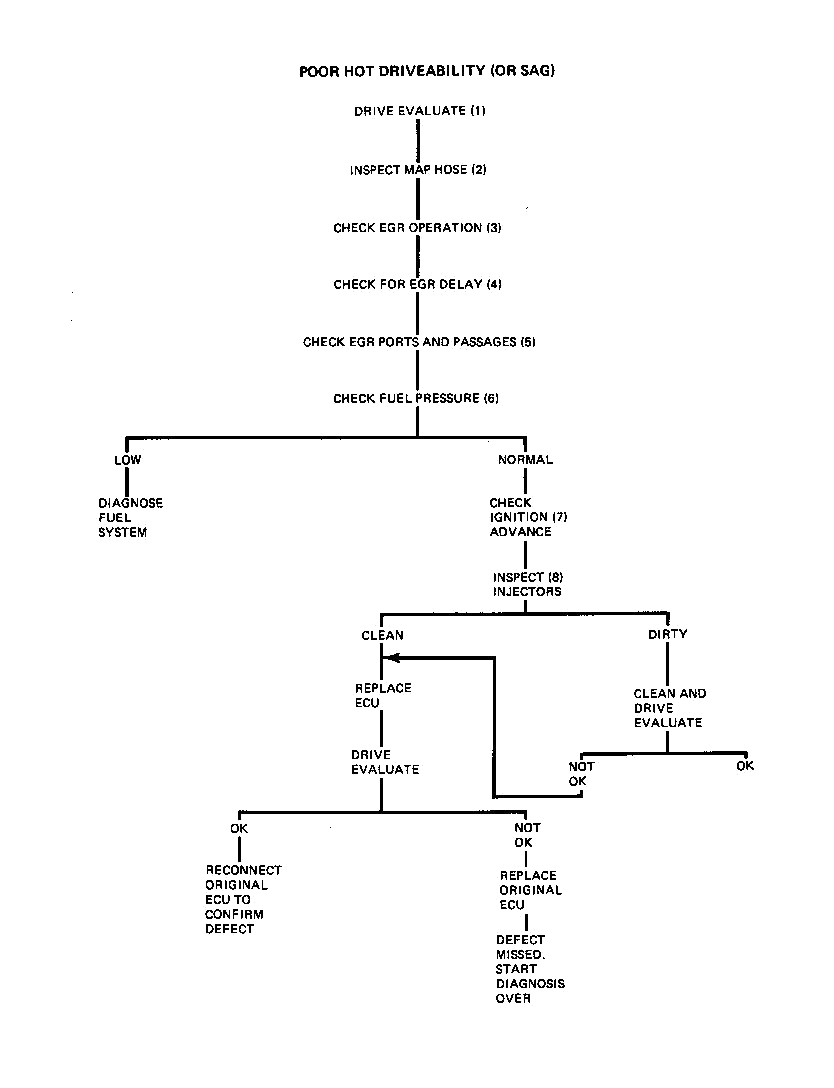
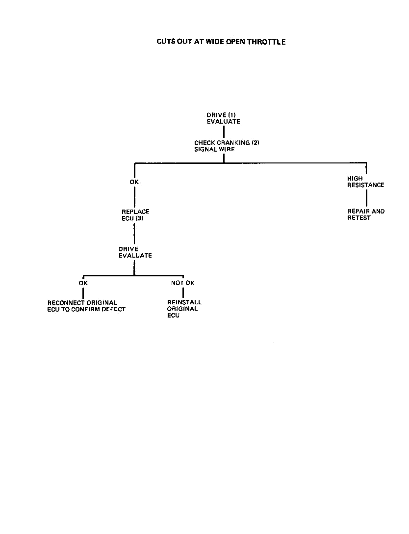
Cuts out at wide open throttle |
Back to the top |
1. The first step in any diagnosis should be an evaluation of the problem. In the case of driveability problems, this is especially important so that driveability improvements can be judged.
2. The WOT signal from TPS is used by the ECU for two different purposes:
a. to shut off the injectors during cranking to clear a flooded engine;The 12 purple wire from the ECU to the starter solenoid “S” terniftial is used for both of these functions:
a. During cranking, a voltage signal is sent through the 12 purple wire to lock in the cranking pulse width. When simultaneous signals are received from ~ the fl’S and starter solenoid, the injectors are deactivated.3. The only other component which can cause this condition is the ECU. The lack of a WOT signal from the TPS will not cause a stall since the MAP line is at zero (or nearly zero), providing a wide pulse width but not as wide as the WOT. pulse width. This results in a loss of performance but not a stall. Replace the ECU on a trial basis.
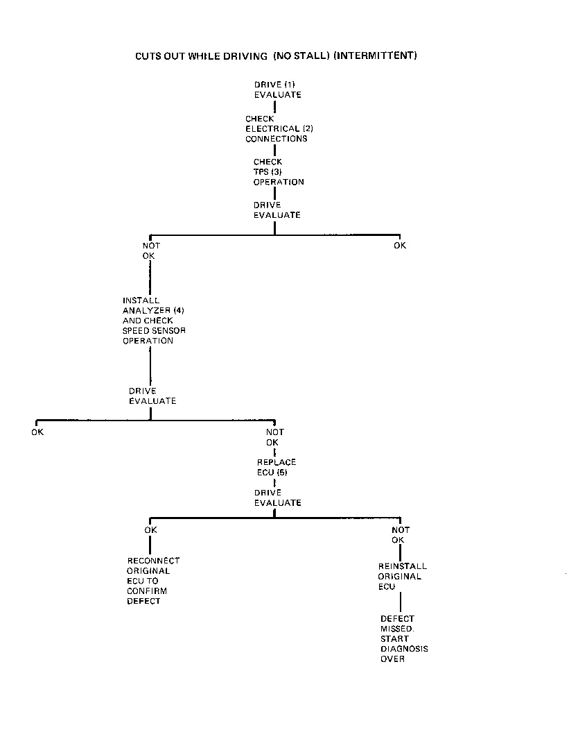
Cuts out while driving (no stall) |
Back to the top |
1. The first step in any diagnosis should be an evaluation of the problem. In the case of driveability problems, this is especially important, so that driveability improvements can be judged.
2. Poor connections which are likely to cause this condition are:
a. Speed Sensor3. Check the TPS for proper operation by rotating the throttle from closed to WOT with the ignition switch ON. The injectors should click 21 times (all clicks will be from one group of injectors). No additional clicks should be heard as throttle is closed.
The TPS can also cause a problem if it skips AE pulses or delivers several at once. To check for this condition, operate the throttle slowly back and forth in the area of normal cruise (1/4 to 3/8 inch off idle) and listen for multiple clicks or “buzz”. This condition requires replacement of the TPS.
NOTE: When WOT is reached, the EGR solenoid will click (when warm). Do not count this as an AE pulse.
Less than 21 clicks indicates a TPS adjustment is necessary. To adjust switch, proceed as follows:
a. Loosen two TPS mounting screws to permit rotation of switch.4. An intermittent signal from the speed sensor will prevent the firing of one group of injectors which feels like the engine “cuts out” momentarily. Install Analyzer 1-25400 and drive the car watching the Analyzer’s indicator lights. Proper operation of the indicator lamps is as follows:
a. Trigger lights - these lamps indicate the connection made by each set of speed sensor contacts. The lights should blink alternately ON and OFF with equal intensity and with a constant rhythm. A lamp OFF, double blink, or a bright or weak blink indicates a speed sensor malfunction.It is important to remember that the trigger and group lights are related in that if the trigger gives an improper signal, the group lights will normally show an identical symptom. For instance, if the trigger does not close one set of contacts, the ECU will not pulse one group of injectors. This is a trigger malfunction and there is nothing wrong with the ECU.
However, if the group lights indicate a malfunction with normal indications from the speed sensor, an ECU malfunction is indicated.
5. If the problem has not been solved at this point, a new ECU should be installed on a trial basis.
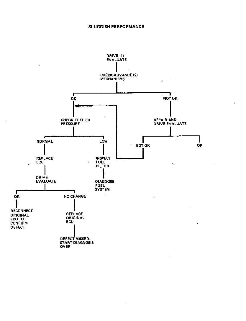
Sluggish performance |
Back to the top |
1. The first step in any driveability diagnosis should be an evaluation of the severity of the complaint so that improvements can be judged.
2. Proper operation of the centrifugal and vacuum advance mechanisms is as important to good driveabiity as proper initial timing setting. The following test is designed to prove that these mechanisms are functioning somewhere near normally.
Chart 1 on Page 50 lists points at which the centrifugal advance mechanism can be tested. The specifications are listed in engine RPM and engine-crankshaft degrees. This test is most easily performed with a tachometer and a timing light with a timing advance meter. The centrifugal advance should be examined with the vacuum hose(s) to the vacuum advance unit disconnected and plugged.
To check centrifugal advance, proceed as follows:
a. Run engine at idle and note timing mark on pulley. Should read initial setting (as specified on underhood label). Timing advance meter will read zero.To check vacuum advance, proceed as follows:
a. Run engine at idle with vacuum advance hose(s) disconnected and plugged.3. Normal fuel pressure is shown in Fig. 1. Low fuel pressure can cause poor performance by creating a lean condition.
Install the fuel pressure and vacuum gages and observe the pressure during the complaint condition. This can be accomplished by connecting an A/C charging line to the pressure gage with a suitable adapter (such as Weatherhead #42x4 connector). The vacuum gage should be teed into the pressure regulator vacuum line. Route the hoses out of the engine compartment to a position where the gages can be read inside the car.
NOTE: This extra length of hose should be used for monitoring fuel pressure only. The short hose supplied with Analyzer 1-25400 must be used for fuel system testing as the additional length will not provide accurate enough gage response.
Low fuel pressure under load is an indication of a fuel supply problem. A collapsed or restricted fuel filter could be the cause. Inspect the filter for this condition. If filter is not obstructed or collapsed, continue fuel system diagnosis as described on Pages 44 through 49.
If fuel pressure is normal the ECU should be replaced on a trial basis.
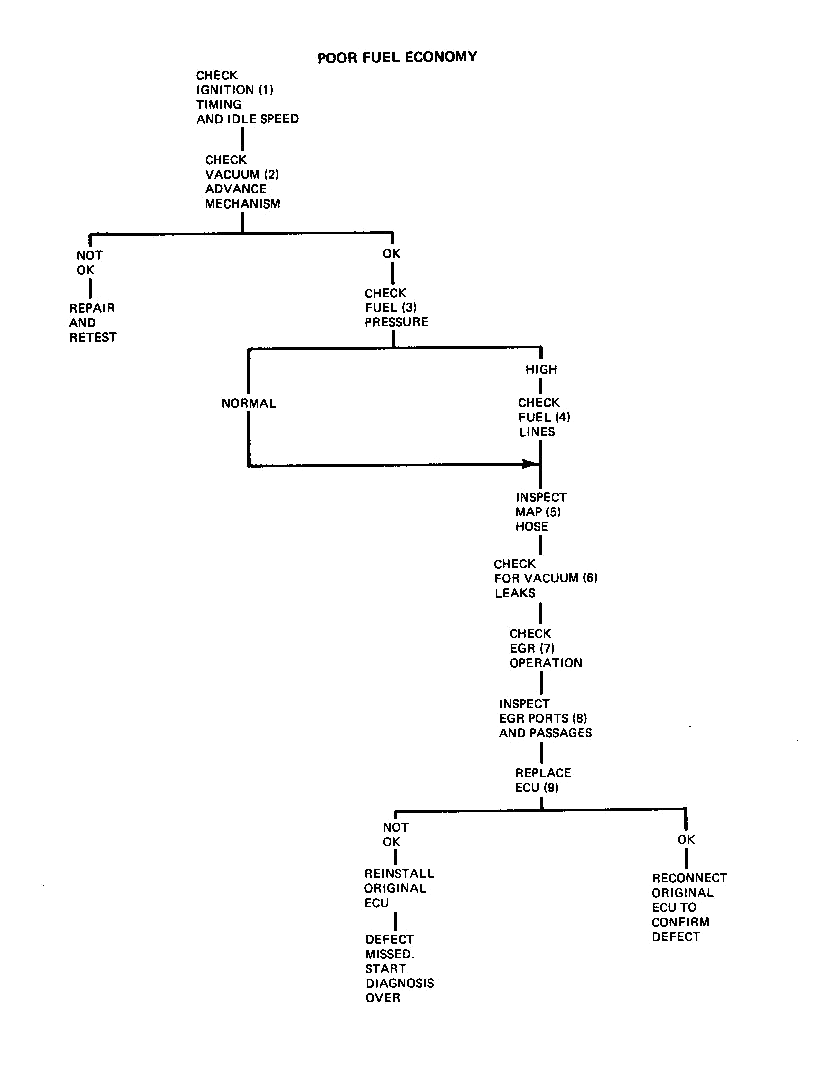
Poor fuel economy |
Back to the top |
1. Improper idle speed and ignition timing are two primary causes of this problem. These adjustments should be set to specification before any further diagnosis is attempted.
2. Proper operation of the vacuum advance mechanism is especially important for good fuel economy. The following test is designed to prove that this mechanism is functioning somewhere near normally.
Chart 2 on Page 51 lists points at which the vacuum advance mechanism can be tested. The specifications are listed in engine-crankshaft degrees. This test is most easily performed with a tachometer and a timing light with a timing advance meter.
To perform this test, proceed as follows:
a. Disconnect vacuum advance hose and run engine at idle. Note timing mark on pulley. Should be initial setting (as specified on underhood label). Advance meter will read zero.3. High fuel pressure will cause a greater than normal quantity of fuel to be delivered through the injectors. Normal fuel pressure is shown in Fig. 1.
4. High fuel pressure proves the capabilities of the chassis pump and isolates the problem to either a malfunctioning pressure regulator or restriction in the return hose. To check these components, remove the fuel return hose from the pressure regulator and run a line between the regulator and a suitable container. Run the engine and observe the fuel pressure. If the pressure is normal, a restricted return line is indicated. However, if the pressure is still high, a noncontrolling regulator is indicated.
5. A leak in the MAP hose will cause richness as it will alter the signal received by the ECU. To check the MAP hose, disconnect the hose at the throttle body and connect a hand vacuum pump such as J-23738 to the hose. Develop a vacuum of 15” in the hose and check for leak down. A damaged hose can be replaced without replacing the entire line.
Also check the vacuum hose at the fuel pressure regulator as a leak in this line will alter the MAP signal as well as increase the fuel pressure.
6. Vacuum leaks at the throttle body will alter the MAP signal the same as a leaking hose. Inspect the throttle body, especially the junction between the throttle body and throttle body adapter for this condition.
7. Too much EGR will cause poor fuel economy by requiring greater throttle openings for acceptable performance.
A “quick check” of the EGR system function should be performed as follows:
a. With engine running, operate throttle. Diaphragm should raise as throttle is opened.The amount of EGR delivered to the intake manifold is proportional to the size of the opening in the orifice.gasket located between the transducer and the manifold, Fig. 6. The size of the orifice can be determined by the configuration of the notches as shown in Fig. 7. This identification can be made without removing the valve and should be done at this time.
8. As described above, the timing and quantity of EGR gases is critical to proper performance. If the “quick check” indicates a blockage, the following procedure should be performed. In addition, a partial blockage condition should be investigated after the “correct parts” determination has been made in step 7. Remove the throttle body and inspect the following:
a. EGR signal port in throttle body (this is the rectangular port in the right hand throttle bore which is connected to the outer nipple on the right hand side of the throttle body adapter), Inspect this port for any dirt build-up and clean as necessary.9. If no significant defect has been found at this point, a new ECU should be installed on a trial basis.
Static fuel system diagnosis - Part 1 |
Back to the top |
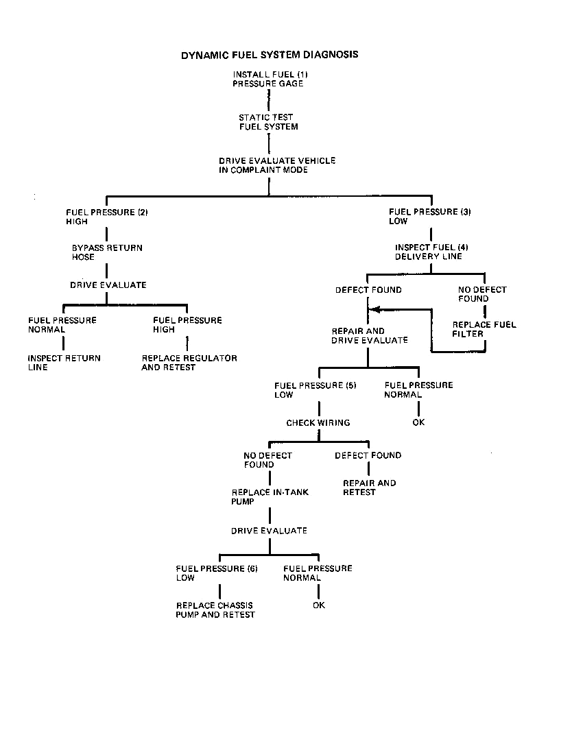
The fuel system diagnosis presented in the following paragraphs will confirm proper fuel system operation. These static tests should be considered only half of the fuel system diagnosis. The dynamic tests immediately following will complete fuel system diagnosis. The static tests will be concerned with proving only if the fuel system is capable of functioning properly. Dynamic testing will determine if the correct pressure is maintained in the fuel rail; that is, is it functioning properly.
This diagnosis is a “decision tree” approach to the material previously published as step 17 of the diagnosis with EEL Analyzer 1-25400. It is intended for use when the Analyzer is not already hooked-up.
1. All fuel pressure observations for these tests are made with the fuel pressure gage from Analyzer J-25400 with only the hose provided. Additional hose will alter fuel pressure readings although precise values have been held to a minimum.
2. Fuel pump operation is normally for one second after the ignition switch is turned ON unless the engine is cranked or running. The ECU is responsible for this control.
Pump operation is confirmed by listening for a one second “whine” of the chassis pump. The noise of the in-tank pump is overshadowed by the chassis pump. We can assume its operation at this point.
3. If fuel pressure is developed it should be maintained. Watch the fuel pressure gage for a drop of more than 5 psi in 2 minutes. Less drop indicates a tight fuel system; proceed to dynamic tests.
4. A pressure drop of more than 5 psi in 2 minutes indicates a fuel system leak. If no external leaks are evident, pinch the fuel return hose at the regulator and cycle the ignition switch (turn ON—OFF--ON—OFF). The pinched hose represents the restriction normally provided by the pressure regulator. If pressure holds, this indicates that the regulator is unable to provide a restriction and is allowing the pressure to drain back to the tank. This indicates that regulator replacement is required.
NOTE: If pressure becomes normal when hose is released, this indicates the foreign material that was holding the regulator off its seat has temporarily been cleaned off. If this material is too big to pass into the return hose, it will remain in the regulator and could cause this problem to reoccur. Since there is no way of knowing the size, the regulator should be replaced regardless.
5. If the pressure drops with the return line pinched, this proves that the pressure is not being lost through the return line and it is either going back through the chassis pump or through an open injector. To determine which of these problems exists, build up pressure by cycling the ignition switch and pinch both supply and return hoses. This locks the pressure in the fuel rail, and if pressure now drops, it is definitely going through an open injector. Inspection of the injectors and spark plugs will indicate faulty injectors.
If the pressure holds with both lines pinched, a check valve failure in the chassis pump is indicated. Replace the pump for this condition.
6. If the pumps operate but no pressure is indicated on the gage, pinch off the fuel return hose at the regulator and cycle the ignition switch.
High fuel pressure with the return line pinched indicates that the chassis pump is capable of creating pressures, but the regulator is unable to provide a restriction and is allowing the pressure to drain back to the tank. This indicates that regulator replacement is required.
NOTE: If pressure becomes normal when hose is released, this indicates the foreign material that was holding the regulator off its seat has temporarily bIâ cleaned off. If this material is too big to pass into the return hose, it will remain in the regulator and could cause this problem to reoccur. Since there is no way of knowing the size, the regulator should be replaced regardless.
7. Low (or no) fuel pressure with the return hose pinched indicates that for some reason the pumps cannot create pressure. Test the output of the in-tank pump by disconnecting the inlet line to the chassis pump and cycling the ignition switch (run fuel into a suitable container).
8. If no fuel is pumped from the in-tank pump, either the 14 dark green feed wire between the chassis and in-tank pump is open or the pump is defective. Inspect this wire and if no defects are found, replace the in-tank pump.
9. Fuel flow from the in-tank pump confirms its proper operation. Connect the chassis pump inlet line and disconnect the outlet line. Cycle the ignition switch (run fuel into a suitable container). If a large quantity of fuel is not pumped, replace the chassis pump.
10. A large fuel flow is expected from the chassis pump. If this is evident, but no fuel pressure is indicated in the rail, a complete blockage of the fuel supply line is indicated.
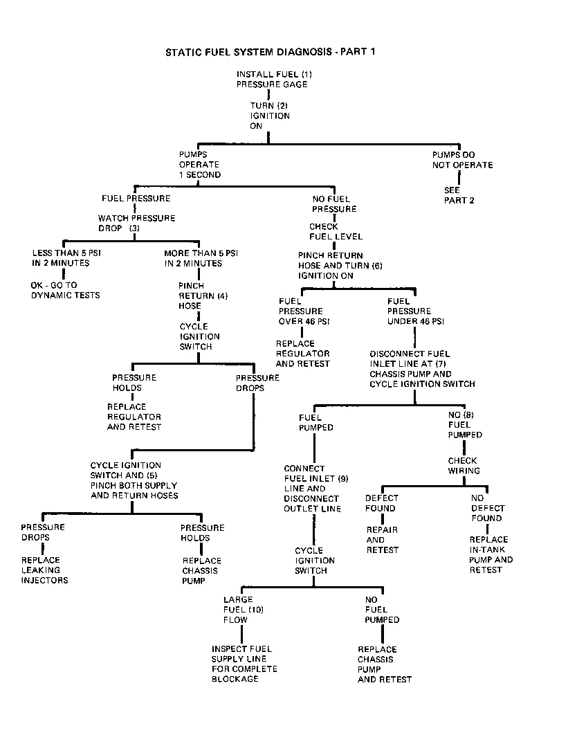
Static fuel system diagnosis - Part 2 |
Back to the top |
1. All fuel pressure observations for these tests are made with the fuel pressure gage from Analyzer 1-25400 with only the hose provided. Additional hose will alter fuel pressure readings although precise values have been held to a minimum.
2. Fuel pump operation is normally for one second after the ignition switch is turned ON unless the engine is cranked or running. The ECU is responsible for this control.
11. If the fuel pumps do not operate for the one second interval, an electrical problem is indicated. Check the 10 amp in-line fuel pump fuse (20 amp EFI fuse on 1977 C cars). Also check 20 amp “Gages-Trans” fuse on 1977 C cars. If fuse is blown, replace fuse, turn ignition switch ON, and again listen for pump operation.
12. If fuse blows immediately, a short in wiring in circuit #827 or 120 is indicated. Inspect the entire length of this wire, repair and retest.
13. If the fuse does not blow, the possibility of an intermittent short still exists. Inspect the wiring in circuits #827 and 120 beCore proceeding with test.
If pumps now operate, continue diagnosis — Part 1 at “Pumps Operate”.
14. Inoperative fuel pumps with a good fuse (ECU feed) indicates an ECU output or wiring harness problem. Check for voltage at the chassis pump 14 dark green (feed) wire.
15. Voltage to the pump isolates the problem to either the chassis pump or the ground wire. If the ground circuit (wire and connections) is satisfactory, replace the chassis pump and retest.
16. No voltage at the chassis pump isolates the problem to either no ECU output or an open in circuits #827 and 120 between the ECU and the pump. Check for voltage at terminal “C” of the blue 10 way connector at the ECU with a 12 volt test light (connectors still attached). This is the ECU output signal and voltage here indicates a wiring problem in circuits #827 or 120 between this point and the chassis pump. Repair and retest.
17. No voltage out of the ECU requires confirmation of an input signal before the ECU can be condemned. Check for voltage at terminal “H” of the blue 10 way connector of the ECU (connector still attached). Voltage at this terminal indicates an ECU replacement is necessary. No voltage isolates the problem to an open circuit in circuit #807 between the fuse and the ECU. Also check 20 amp “Gages-Trans” fuse on 1977 C cars.
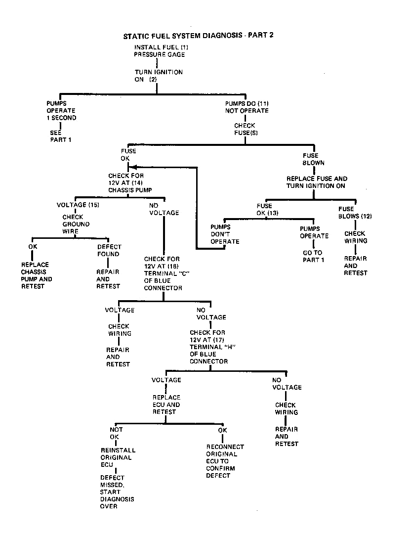
Dynamic fuel system diagnosis |
Back to the top |
The following fuel system diagnosis is designed to diagnose the cause of abnormal operating pressures.
1. Install the fuel pressure and vacuum gages and observe the pressure during the complaint condition. This can be accomplished by connecting an A/C charging line to the pressure gage with a suitable adapter (such as Weatherhead #42x4 connector). Tee the vacuum gage into the pressure regulator vacuum line. Route the hoses out of the engine compartment to a position where the gages can be read inside the car.
NOTE: This extra length of hose should be used for monitoring fuel pressure only. The short hose supplied with analyzer 1-25400 must be used for component test-big as the additional length will not provide accurate enough gage response.
Normal fuel pressure is shown in Fig. 1.
2. High fuel pressure can only result from a restriction in the return hose or a malfunction in the pressure regulator. To define which condition exists, bypass the return line with a length of hose back to the fuel tank and drive evaluate the car (not necessary to drive if high at idle). If fuel pressure is now normal, the restriction is in the return line. If high pressure still exists, a defective regulator is indicated.
3. Many complaint conditions can be caused by low fuel pressure. Low pressure can be caused by the fuel delivery system not being able to supply the volume of fuel required under a load condition. This is due to a partial failure within the system which prevents the regulator from providing a small enough restriction to raise the fuel pressure. This prevents the injectors from delivering adequate fuel.
4. A restricted fuel delivery line can cause low pressure by restricting the amount of fuel available at the rail. Inspect this line for kinks or restrictions. A blockage at the fuel filter resulting from a collapsed or contaminated filter should also be considered as part of the delivery line inspection.
5. Low pressure produced by the pumps can be caused by an inoperative in-tank pump. This condition will allow the system to operate normally at moderate ambient temperatures, but fail at high ambient temperatures. Inspect the 14 dark green wire between the chassis and in-tank pumps and the ground wire. If no defect is found, replace the in-tank pump and retest.
6. If fuel pressure remains low, replace the chassis pump and retest.