Technical information about the '76 to '79 Cadillac Seville. Subjects are "EFI Diagnosis", "'76 - '79 body parts", "Frame diagram" and "Electrical troubleshooting".
Important Safety Notice |
Back to the top |
Proper service and repair is important to the safe, reliable operation of all motor vehicles. The service procedures recommended by Cadillac and described in this service manual are effective methods of performing service operations. Some of these service operations require the use of tools specially designed for the purpose. The special tools should be used when and as recommended.
It is important to note that this manual contains various Warnings, Cautions and Notes which should be carefully read in order to minimize the risk of personal injury to service personnel or the possibility that improper service methods will be followed which may damage the vehicle or render it unsafe. It is also important to understand that these Warnings, Cautions and Notes are not exhaustive. Cadillac could not possibly know, evaluate and advise the service trade of all conceivable ways in which service might be done or of the possible hazardous consequences of each way. Consequently, Cadillac has not undertaken any such broad evaluation. Accordingly, anyone who uses a service procedure or tool which is not recommended by Cadillac must first satisfy himself thoroughly that neither his safety nor vehicle safety will be jeopardized by the service method he selects.
How to use this book |
Back to the top |
NOTE
The first three pages contain general information about electrical troubleshooting, symbols, and fuse and bulb information. Read these pages to be sure you know the meaning of the symbols used in this book.
Each Wiring Diagram shows when and how the circuit gets its power, what the current path is to the circuit components, and where the components are grounded. The component name is usually found to the right of each component (underlined), and some important operating information is given. Wire gauge and colors are also listed.
The Text Page contains four pieces of information: Component Location (given in chart form); Troubleshooting Hints, suggested short-cuts to find the problem (given in effect-cause form); Figures, which give a visual location for connectors and components; and, for more complex systems, Circuit Operation, a description of the special features of the circuit.
The Ground Page gives a detailed view of complex car ground points.
Prepared By:
Available From:
Cadillac Motor Car Division
Cadillac Stationary Control
Drawer 30091
Lansing, Michigan 48909
Catalog No. - S-1556
Price - $4.50
01 - Troubleshooting |
Back to the top |
1. Check the Complaint : Operate the problem circuit yourself (or watch the customer operate it) to be sure you understand what's wrong. Don't waste time fixing part of the problem!
2. Read the Wiring Diagram : Study the diagram to understand how the circuit is supposed to work. Read the detailed description added in complex diagrams.
3. Find the Problem : Use the Troubleshooting section with each circuit.
4. Make the Repair.
5. Test the Repair: Operate the repaired system in all modes to be sure the whole problem is fixed - not just part.
TROUBLESHOOTING TOOLS
Test Light: a 12-volt light bulb with a set of test leads.
Uses: Voltage Check, Short Check
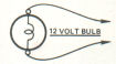
Figure 1-1 - Test Light
Self-Powered Test Light: a light, battery, and set of test leads wired in series.
Uses: Continuity Check, Ground Check
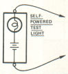
Figure 1-2 - Self-Powered Test Light
Jumper Wire: a circuit breaker with a length of wire and clips on each end.
Uses: Bypassing Open Circuits and Loose Connections.
WARNING: Never use a jumper wire across any load (motors, ect.). This direct battery short may cause injury or fire.

Figure 1-3 - Jumper Wire
VOLTAGE CHECK:
1. Connect one lead of test light to a known good ground or negative (-) battery terminal.
2. Connect other test light lead to connector or component terminal. Bulb lights when voltage is present.
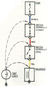
Figure 1-4 - Voltage Check
SHORT CHECK (blown fuse):
1. Remove fuse and disconnect all loads.
2. Connect test light across fuse terminals.
3. Beginning near the fuse block, move the harness from side to side while watching the test light.
4. Test Light ON: Short to ground in the wiring. Somewhere in that area the wire insulation has worn away and circuit is grounding.
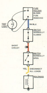
Figure 1-5 - Short Check
CONTINUITY CHECK:
CAUTION: Be sure no voltage is present in circuit during this test.
Connect one lead of self-powered test light at one end of the circuit, and the other lead at the other end. Test light glows if there is continuity.
Switches can be checked in the same way.
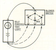
Figure 1-6 - Continuity Check
GROUND CHECK
CAUTION: Be sure no voltage is present in circuit during this test.
Connect one lead of self-powered test light to a known good ground, and the other lead to the wire in question.
- Light ON: ground is good
- Light OFF: no ground
GENERAL TROUBLESHOOTING HINTS
If several unrelated circuits fail at the same time, chances are the power (fuse) or ground circuit is bad.
Use the Fuse Information to find what circuits are powered through each fuse.
Use the Ground Page to find which circuits have a common ground.
NOTE: Ground page shows only complex eyelet grounds. Circuits with single or component grounds are shown on circuit diagram page.
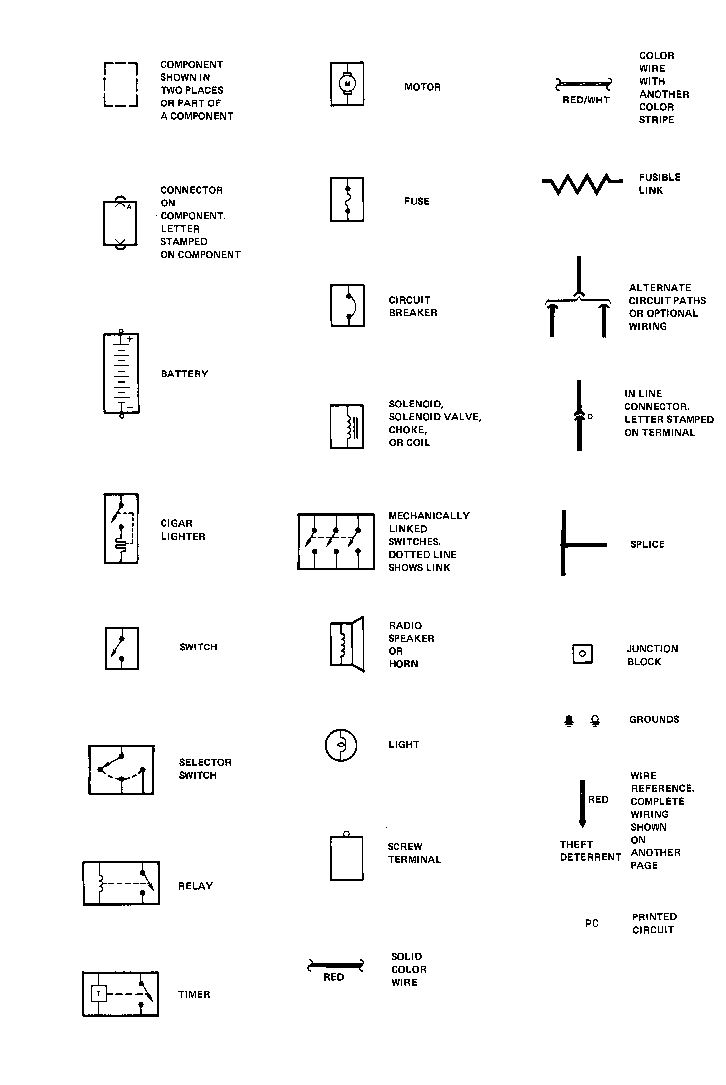
02 - Symbols |
Back to the top |
NOTE: All switches shown in this manual are in "at rest" position.
NOTE: Additional information
CAUTION: Possible damage to vehicle or equipment
WARNING: Possible injury to mechanic
03 - Fuse / Power / Light data |
Back to the top |
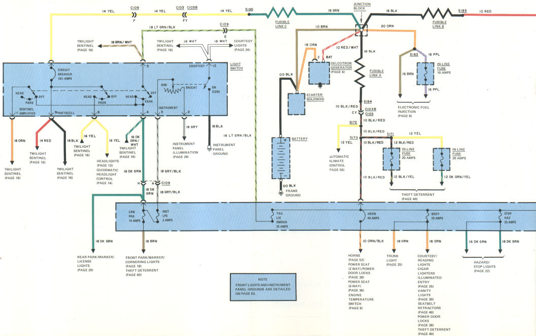
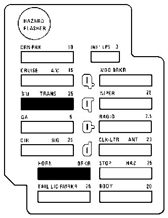
Power Bus Information
The GENERATOR and BATTERY connect together at the JUNCTION BLOCK. The JUNCTION BLOCK is the Power Distribution point for car circuits.
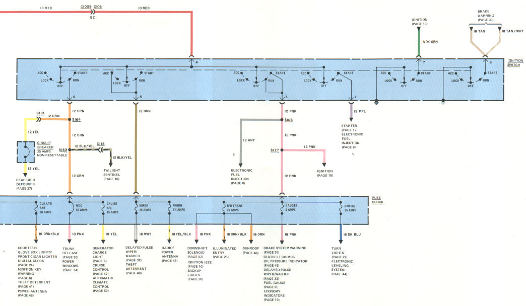
The IGNITION SWITCH, LIGHT SWITCH, TAIL LIC RMRKR, BODY, STOP HAZ, CLK LTR ANT fuses and HORN circuit breaker are hot at all times, as well as some in-line fuses.
Fusible Links
A FUSIBLE LINK is a length of wire four (4) gauges smaller than the cable it protects. The FUSIBLE LINK insulation is different from other wires. In case of a short, the FUSIBLE LINK melts, opening the circuit to protect electrical components.
CAUTION: Replace fusible links with an exact replacement only. Make tight crimp joints and hot solder joints for good connections.
Self-Resetting Circuit Breakers
Some circuits are protected by self-resetting circuit breakers. Each circuit breaker has a set of contacts connected by a bi-metallic strip. If the strip becomes too hot (overcurrent), the bi-metallic strip bends out of shape, opening the circuit. When the bi-metallic strip cools down, the contacts are closed, and current flows through the circuit breaker again.
The circuit breaker cycles (opens and closes) as long as the overcurrent exists.
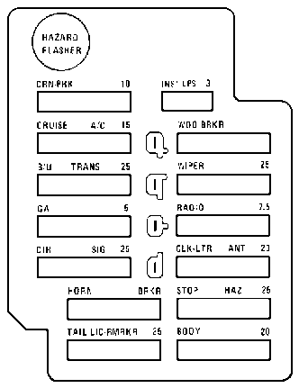
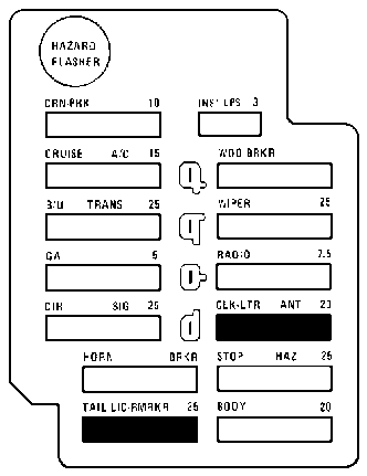
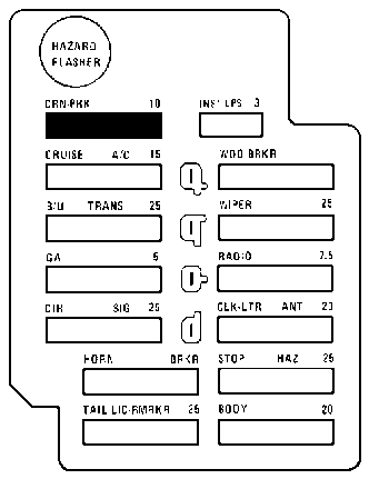
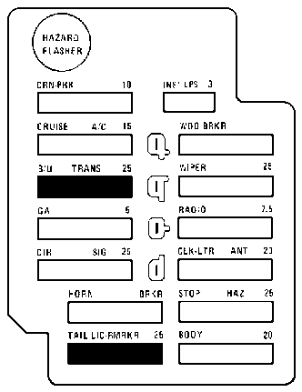
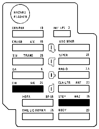
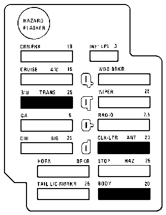
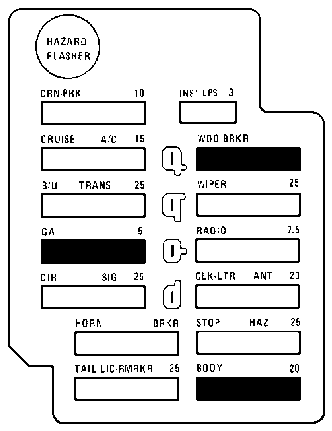
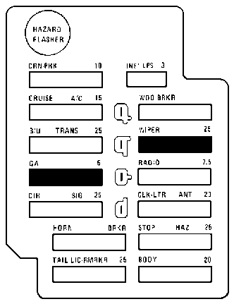
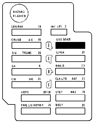
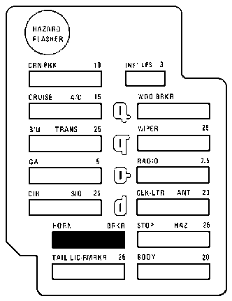
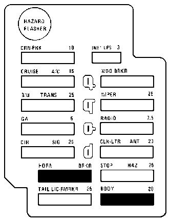
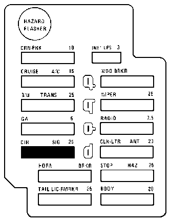
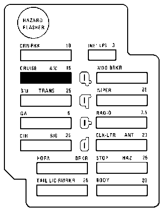
| Fuse Name | Amp Rating | Circuits protected |
| CRN PRK | 10 | Cornering, Front Marker, Park, Ash Tray Lights, Theft Deterrent |
| CRUISE A/C | 15 | Automatic Climate Control; Cruise Control, Generator Charging Light |
| B/U TRANS | 25 | Backup Lights, Downshift Solenoid, Ignition (ESS), Illuminated Entry, Sunroof |
| GA | 5 | Warning Lights, Fuel Economy Indicators, Fuel Gauge |
| DIR SIG | 25 | Turn Lights, Electrical Leveling System |
| HORN CIRCUIT BREAKER | 40 | Horns, Power Seats, Power Door Locks, Stop: Engine Temperature Indicator |
| TAIL LICC RMRKR | 25 | Park, Marker, License, and Cornering Lights, Twilight Sentinel |
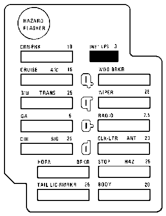
| INST LPS | 3 | Instrument Panel Illumination |
| WDO CIRCUIT BREAKER | 40 | Power Windows, Trunk Pull Down |
| WIPER | 25 | Delayed Pulse Wiper / Washer, Theft Deterrent |
| RADIO | 7.5 | Radio / Power Antenna |
| CLK LTR ANT | 20 | Radio / Power Antenna, Theft Deterrent, Ignition Key Warning, Courtesy and Glove Box Lights, Cigar Lighter; Digital Clock |
| STOP HAZ | 25 | Hazard / Stop Lights |
| BODY | 20 | Vanity, Courtesy, Reading, and Trunk Lights, Cigar Lighters, Illuminated Entry, Belt Retractors, Power Door Locks, Theft Deterrent |
| Function | Bulb number | Candlepower |
| Accessory Switch | 1445 | .7 |
| Ashtray Illumination | 1445 | .7 |
| Backup Light | 1156 | 32 |
| ATC Illumination | 168 | 3 |
| Clock | 1895 | 2 |
| Cornering Light | 1156 | 32 |
| Courtesy - Instrument Panel | 906 | 6 |
| Courtesy - Front Doors | 562 | 6 |
| Courtesy - Rear Doors | 562 | 6 |
| Cruise Control Indicators | 161 | 1 |
| Door Lock Illumination | 558 | 2.5 |
| Engine Temperature Indicator | 194 | 2 |
| Fuel Economy Indicator | 161 | 1 |
| Fuel Gauge | 194 | 2 |
| Generator Indicator | 194 | 2 |
| Headlight - Inner | 4651 | 50W |
| Headlight - Outer | 4652 | 60W / 40W |
| Headlight Switch | 1816 | 3 |
| High-Beam Indicator | 194 | 2 |
| Instrument Cluster | 194 | 2 |
| Instrument Panel Compartment | 1816 | 3 |
| License | 194 | 2 |
| Low Brake Warning Indicator | 194 | 2 |
| Oil Pressure Warning | 194 | 2 |
| Windshield Washer Fluid Level | 161 | 1 |
| Reading Light | 912 | 12 |
| Turn / Park | 1157 | 32 / 3 |
| Radio Illumination | 1893 | 2 |
| Radio - Stereo w / Integral Tape Player Illumination | 1893 | 2 |
| Trunk Compartment | 1003 | 15 |
| Rear Deck Lid Indicator | 161 | 1 |
| Rear Grid Defogger Indicator | 1445 | .7 |
| Seat Belt Indicator | 194 | 2 |
| Theft Deterrent Indicator | 194 | 2 |
| PRND21 Indicator | 161 | 1 |
| Front Marker Light | 194A | 2 |
| Rear Marker Light | 194 | 2 |
| Spot Light - Front Compartment | 1004 | 15 |
| Turn / Stop Light | 1157 | 32 / 3 |
| Turn Signal Indicator | 194 | 2 |
| Vanity Mirror | 562 | 6 |
| Windshield Wiper Switch Illumination | 194 | 2 |
| Water Temperature Warning | 194 | 2 |
| Thermometer Illumination | 194 | 2 |
| Dome Light | 562 | 6 |
| CB Radio Illumination | 1893 | 2 |
| AWG | METRIC |
| 0 | 50 |
| 2 | 32 |
| 8 | 8 |
| 10 | 5 |
| 12 | 3 |
| 14 | 2 |
| 16 | 1 |
| 18 | .80 |
| 20 | .50 |
| 24 | .22 |
04 - Power distribution |
Back to the top |
05 - Charge / Key warning buzzer / Stop: Engine temperature indicator |
Back to the top |
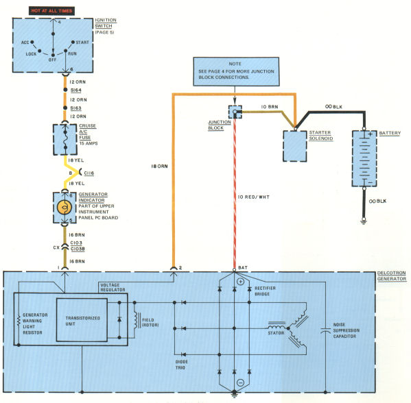
CIRCUIT OPERATION
With the IGNITION SWITCH in Run, BATTERY voltage is applied through the CRUISE A/C FUSE and the GENERATOR INDICATOR to terminal 1 of the VOLTAGE REGULATOR. The GENERATOR WARNING LIGHT RESISTOR draws current and the WARNING LIGHT glows. Current flows through the REGULATOR to the GENERATOR FIELD WINDING.
The rotating field and the rectifier diodes produce a DC generator output voltage at the BAT terminal. A DC voltage is also applied at the field winding, through the Diode Trio.
Field current is provided by the Diode Trio or from the BATTERY through the GENERATOR INDICATOR.At low engine speed, current flows from the BATTERY through the GENERATOR INDICATOR to the FIELD WINDING. The GENERATOR INDICATOR is lit whenever the BATTERY supsupplies field current. As the engine speed increases, the generator output voltage increases and the field current is supplied by the GENERATOR through the DIODE TRIO. When the voltage on each side of the GENERATOR INDICATOR is about the same, the light goes out.
3. It is important to remember that the trigger and group lights are related in that if the trigger gives an improper signal, the group lights will normally show an identical symptom. For instance, if the trigger does not dose one set of contacts, the ECU will not activate one group of injecton. This is a trigger malfunction and there is nothing wrong with the ECU. However, if the group lights indicate a malfunction with normal indications from the speed sensor, an ECU malfunction is indicated.
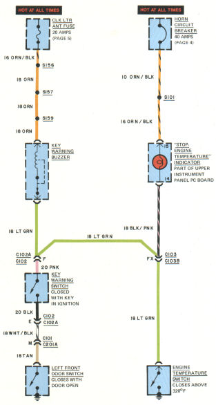
Key Warning Buzzer
The KEY WARNING BUZZER sounds whenever the key is in the ignition switch and the left front door opens.
The closed IGNITION KEY SWITCH and LEFT FRONT DOOR SWITCH also provide a ground path (through the LT GRN wire) for the "Stop: Engine Temperature" INDICATOR, lighting the bulb as a test.
Engine Temperature Indicator
The "Stop: Engine Temperature INDICATOR lights:
1. if the driver's door opens and the key is in the IGNITION SWITCH (bulb test)
2. if the engine block temperature exceeds 320°F (160°C).
The closed ENGINE TEMPERATURE SWITCH also provides a ground path (through the LT GRN wire) for the KEY WARNING BUZZER. The buzzer sounds until temperature drops below 240°F (116°C).
TROUBLESHOOTING
Most Common Charge System Problems:
- Dead BATTERY
- BATTERY using too much water
- GENERATOR INDICATOR lit at normal speed
IMPROPER CHARGING
- Check generator belt tension.
- Check battery charge indicator.
- Check BATTERY if indicator is dark whether green dot is visible or not.
- Do not charge BATTERY if indicator is lit. Replace BATTERY.
- Check for tight, clean connections at GENERATOR and BATTERY.
NOTE: Read shop manual for detailed charging system tests.
"STOP: ENGINE TEMPERATURE" INDICATOR WON'T LIGHT
COMPONENT LOCATION
| Page/Figure | ||
| Diode Trio | Inside generator slip ring end frame | |
| Engine Temperature Switch | Lower rear of engine, above transmission | |
| Generator Warning Light Resistor | Inside generator slip ring end frame | |
| Key Warning Buzzer | Dash harness, near steering column | |
| Noise Suppression Capacitor | Inside generator slip ring end frame | |
| Rectifier Bridge | Inside generator slip ring end frame | |
| Voltage Regulator | Inside generator slip ring end frame | |
C101 |
Fuse block |
5-1 |
| C102 | Steering column | 7-1 |
| C102A | Steering column | 7-1 |
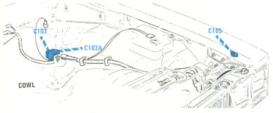
| C103 | Bulkhead, behind fuse block | 5-1 |
| C103B | Bulkhead, engine harness | 5-1 |
| C116 | Under dash | 16-1 |
| C201A | Fuse block | 5-1 |
06 - Electronic fuel injection / Fuel gauge |
Back to the top |
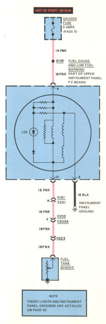
CIRCUIT OPERATION
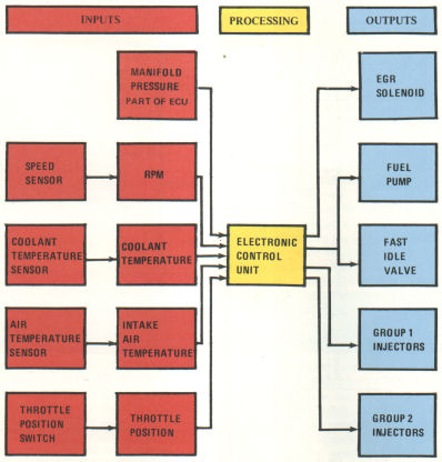
The EFI controls fuel injection and limits emissions by balancing the air/fuel mixture.
NOTE: The normal engine timing advance is 10° before TDC (8° in California).
Figure 6-1 shows inputs which govern the outputs of the Electronic Control Unit.
TROUBLESHOOTING
For detailed procedures, read "Electronic Fuel Injection" in 1978 Cadillac Service Manual.
COMPONENT LOCATION
| Page/Figure | ||
| Air Temperature Sensor | Center rear engine | |
| Coolant Temperature Sensor | Front left engine | |
| EGR Solenoid | Top engine | |
| Electronic Control Unit | Under dash, below radio | |
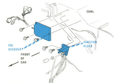
| ESS Decoder | Bulkhead, near windshield washer and wiper | 8-1 |
| Fast Idle Valve | Throttle body | |
| Fuel Pump (frame) | Frame, near left rear wheel | |
| Fuel Pump (tank) | Fuel tank | |
| In-Line Fuse | Dash harness | |
| Junction Block | Bulkhead, near windshield washer and wiper motor | 8-1 |
| Throttle Position Switch | On throttle assembly | |
C101 |
Fuse block |
5-1 |
| C107 | EFI manifold harness, rear of engine | |
| C129 | EFI electronic control unit | |
| C130 | EFI electronic control unit | |
| C131 | EFI electronic control unit | |
| C132 | EFI electronic control unit | |
| C201 | Fuse block | 5-1 |
| C202 | Rear body harness | 14-1 |
| C202A | Rear body harness | 14-1 |
| C220 | Fuel tank fuel pump | |
| C223 | Chassis mounted fuel pump |
07 - Ignition |
Back to the top |
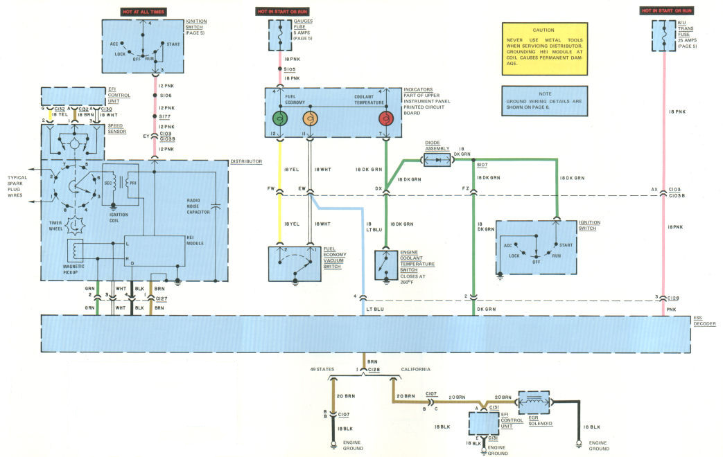
CIRCUIT OPERATION
Distributor
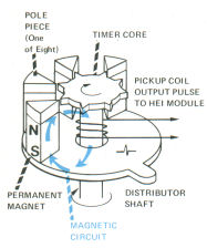
With the IGNITION SWITCH in Start or Run, current flows to the DISTRIBUTOR through the PNK wire. As the engine turns, the TIMER CORE (figure 7-1) rotates. This makes and breaks a magnetic circuit each time a spark plug fires.
When the distributor shaft rotates, the CORE teeth come together with the POLE teeth, and magnetic flux flows from the PERMANENT MAGNET through the MAGNETIC PICKUP COIL and back to the PERMANENT MAGNET. As the rotating CORE teeth pass by the POLE teeth, the magnetic flux drops, causing a voltage signal in the MAGNETIC PICKUP COIL. This voltage is sensed and amplified by the HEI MODULE. The HEI MODULE switches a high current signal through the IGNITION COIL PRIMARY. The PRIMARY current creates magnetic energy, which is stored in the iron frame of the COIL.
As the CORE teeth come together with the POLE teeth again, the magnetic flux rises, and a different voltage signal (opposite polarity) is generated in the MAGNETIC PICKUP COIL. This signal causes the HEI MODULE to interrupt the PRIMARY current. This collapses the magnetic field in the COIL, generates a high voltage in the IGNITION COIL SECONDARY, and fires one spark plug.
NOTE: The transistorized HEI MODULE is a high-energy ignition unit which controls spark triggering, switching, current limiting (about 6 amps), dwell control (varied directly with RPM) and distributor pick-up.
CAUTION: Because of the high HEI voltage (35,000 volts), special 8mm diameter spark plug wires with silicone insulation are used. Silicone insulation is soft and must be handled with extreme care. Replace any scratched or nicked wire.
The RADIO NOISE CAPACITOR suppresses noise generated in the DISTRIBUTOR.
The SPEED SENSOR generates two electrical signals directly related to RPM. These signals are sent to the EFI ELECTRONIC CONTROL UNIT (1), synchronizing the INJECTOR GROUPS with the timing of the intake valves (phasing) and (2) scheduling fuel consumption.
Electronic Spark Selection (ESS)
The ESS system advances or retards the IGNITION, depending on various operating conditions. Fuel economy is improved at cruising speeds and exhaust emissions are reduced. Restarting of a hot engine is improved.
Figure 7-2 shows the different ESS operating modes.
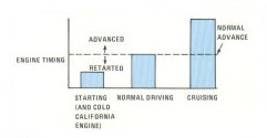
There is no change in engine timing during normal city driving. When the engine is cold (below about 130°F or 54°C), California cars have retarded spark. (This decreases catalytic converter warm-up time and reduces emissions.) 49-States cars have normal spark advance during this operation. When starting engine, the spark is retarded from normal advance on all cars. (This improves hot starting because ignition occurs closer to the beginning of the power stroke.) Spark timing is advanced during driving conditions (improves fuel economy).
The RPM signal (ignition timing) is sent from the MAGNETIC PICKUP COIL to the ESS DECODER. The ESS DECODER output signal is sent on the BLK wire to new 5th pin (terminal D) on the HEI MODULE. This signal either delays or does not delay the interruption of PRIMARY current. The engine start signal is sent to the ESS DECODER (C128, terminal 2) on the DK GRN wire. Engine vacuum (detected by the FUEL ECONOMY VACUUM SWITCH) is sensed by the LT BLU wire at C128, terminal 4).
Engine coolant temperature is indirectly sensed by the ESS through the ELECTRONIC FUEL INJECTION ECU. The COOLANT TEMPERATURE SENSOR is connected to the ECU (see chapter 06 - Electronic Fuel Injection). When the engine is cold, the ECU energizes the EGR SOLENOID, and the exhaust gas recirculation is shut off. The ECU applies about +12 volts to the EGR SOLENOID. On California cars, +12 volts is applied to the ESS DECODER input (C128, terminal 1). On 49-State cars, the input to ESS DECODER is grounded. With the input at ground, the spark is set for normal advance. The DECODER senses this difference, and retards the spark on the cold engine California cars. When the engine warms, the ECU grounds and de-energizes the EGR SOLENOID through C131, terminal E (BLK wire to ENGINE GROUND), and the spark changes to normal advance.
Fuel Economy Indicators
When cruising, or with light throttle acceleration, the FUEL ECONOMY VACUUM SWITCH closes and the green indicator lights. With heavy acceleration the switch opens. The amber indicator lights (heavy fuel consumption). With the engine stopped, the amber indicator lights when the IGNITION SWITCH is turned to Start or Run.
Engine Coolant Temperature Switch
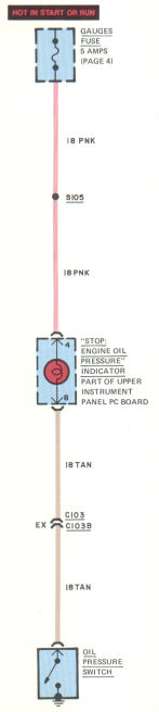
If the engine coolant temperature rises above 260°F (127°C), the ENGINE COOLANT TEMPERATURE SWITCH closes. The red indicator lights. As a bulb check, when the IGNITION SWITCH is turned to Start, current flows from the indicator light through the DIODE ASSEMBLY and to ground through the IGNITION SWITCH.
TROUBLESHOOTING
For detailed troubleshooting, read "ESS Service instructions" in 1978 Service Manual.
COOLANT TEMPERATURE INDICATOR WON'T LIGHT DURING START
- To check DIODE ASSEMBLY, connect lead across terminals DZ and FZ on C103B (short out DK GRN wires). Turn IGNITION SWITCH to Start and watch COOLANT TEMPERATURE INDICATOR.
AMBER FUEL ECONOMY INDICATOR WON'T LIGHT
- Connect lead from terminal EW (WHT wire) on C103B to ground. With engine off, turn IGNITION SWITCH to Start or Run and watch amber light.
COMPONENT LOCATION
| Page/Figure | ||
| Diode Assembly | Dash harness | |
| EFI Control Unit | Under dash, below radio | |
| EGR Solenoid | Top engine | |
| ESS Decoder | Bulkhead, near windshield washer and wiper motor | 8-1 |
| Engine Coolant Temperature Switch | Top front of engine | |
| Fuel Economy Switch | Mounted on center bulkhead connector | |
| HEI Module | Part of distributor | |
| Ignition Coil | Part of distributor | |
| Magnetic Pickup | Part of distributor | 7-1 |
| Radio Noise Capacitor | Part of distributor | |
| Speed Sensor | Part of distributor |
08 - Starter |
Back to the top |
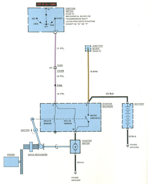
CIRCUIT OPERATION
When the IGNITION SWITCH is turned to Start, current flows through the STARTER SOLENOID windings and the STARTER MOTOR. The motor begins to turn slowly, allowing the gear teeth to mesh. The MOTOR contacts close and BATTERY power bypasses the PULL-IN WINDING and flows directly to the STARTER MOTOR. Current flowing through the HOLD-IN WINDING keeps the STARTER SOLENOID engaged until the engine starts.
When the IGNITION SWITCH is released, current from the IGNITION SWITCH to the HOLD-IN WINDING is cut off. Current from the battery is sent in the reverse direction through the PULL-IN WINDING, but continues in normal direction through the HOLD-IN WINDING. The magnetic force of the HOLD-IN WINDING is canceled by the reverse force of the PULL-IN WINDING. The STARTER SOLENOID releases the DRIVE MECHANISM and opens the MOTOR CONTACTS. STARTER MOTOR current is interrupted.
COMPONENT LOCATION
| Page/Figure | ||
| C103 | Bulkhead, behind fuse block | 5-1 |
| C103B | Bulkhead, engine harness | 5-1 |
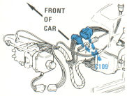
| C109 | Under left dash | 11-2 |
09 - Headlights |
Back to the top |
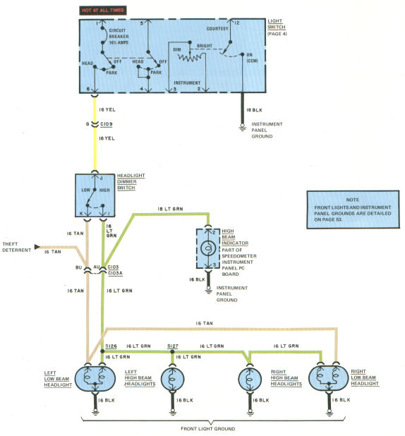
TROUBLESHOOTING
HEADLIGHT CIRCUIT BREAKER CYCLES
- If equipped with TWILIGHT SENTINEL, disconnect SENTINEL AMPLIFIER.
- Check for short in HEADLIGHTS.
GROUP OF LIGHTS IS OUT
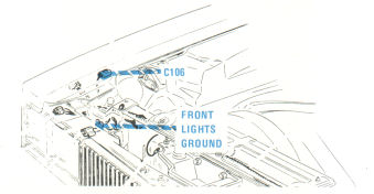
- Check FRONT LIGHTS GROUND.
- Check connections at HEADLIGHT DIMMER SWITCH.
- Check for voltage at LIGHTS and HEADLIGHT DIMMER SWITCH.
10 - Guidematic headlight control |
Back to the top |
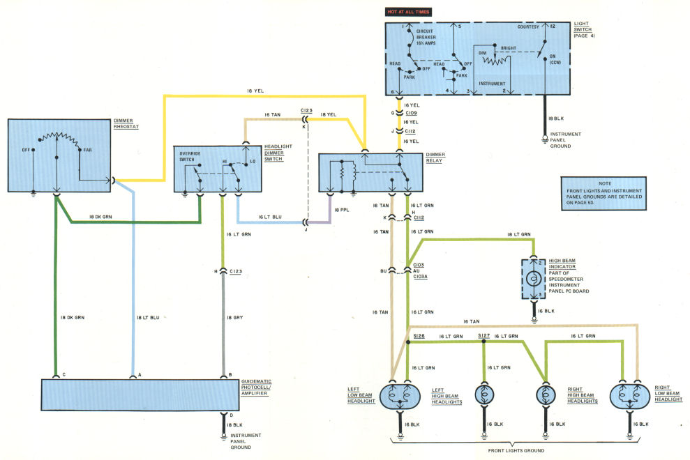
CIRCUIT OPERATION
The GUIDEMATIC system automatically dims the hi beams when oncoming traffic is sensed.
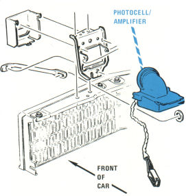
The PHOTOCELL senses light from approaching headlights. PHOTOCELL sensitivity is adjusted by the DIMMER RHEOSTAT.
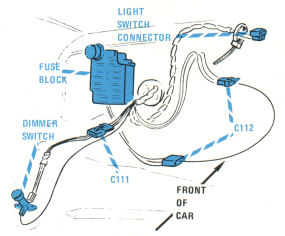
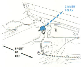
When the PHOTOCELL senses headlights, the AMPLIFIER sends a signal through the GRY wire, through the floor dimmer switch, and through the LT BLU and PPL wires to energize the DIMMER RELAY. The relay switches power to the lo beams.
When the PHOTOCELL senses darkness, the AMPLIFIER interrupts the signal to the DIMMER RELAY (DIMMER RELAY de-energized). The lights switch back to hi beam.
If the floor dimmer switch is slightly depressed, the OVERRIDE SWITCH closes. The amplifier is grounded through the DK GRN wires and the override switch. The high beams are turned on. The high beams can be flashed for signaling by rapidly closing and opening the OVERRIDE SWITCH.
TROUBLESHOOTING
NO HEADLIGHTS
- Check FRONT LIGHTS GROUND (Ground Page).
- Check input voltage to DIMMER RELAY (connector C112, terminal J, YEL wire).
- Check DIMMER RELAY output voltages (connector C112, terminals H and K, LT GRN and TAN wires).
GUIDEMATIC DOESN'T WORK
- Connect GUIDEMATIC PHOTOCELL/ AMPLIFIER terminal D to ground and operate GUIDEMATIC.
- Check AMPLIFIER input voltages (terminals A and C, LT BLU and DK GRN wires).
- Check AMPLIFIER output voltage (terminal B, GRY wire).
11 - Twilight sentinel |
Back to the top |
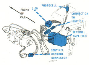
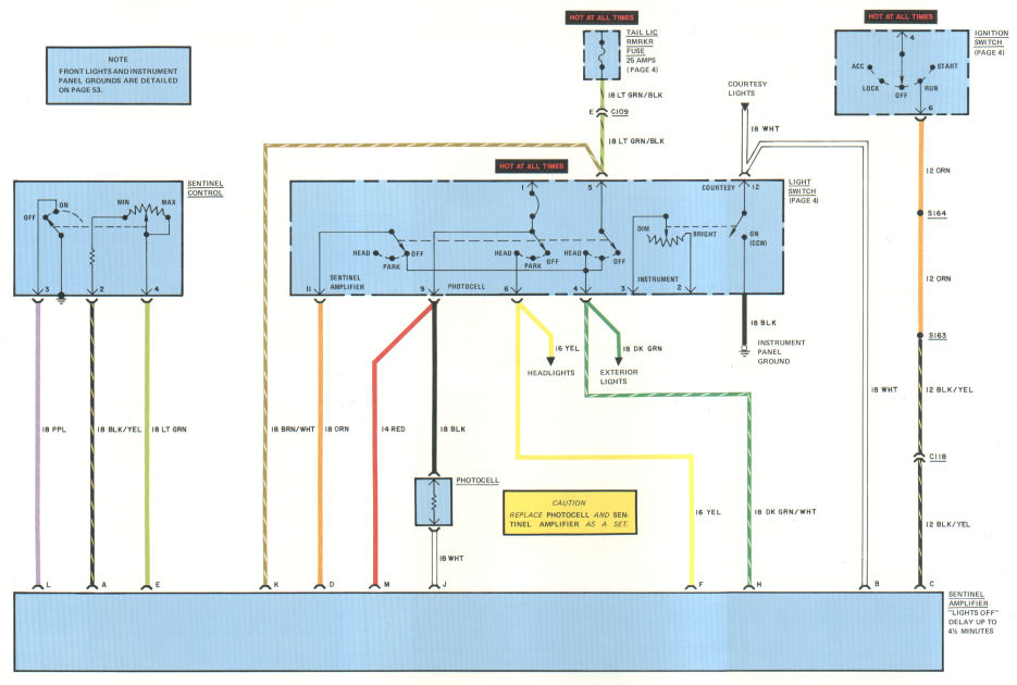
CIRCUIT OPERATION
The TWILIGHT SENTINEL automatically turns the headlights and exterior lights on at dusk, and off at dawn. It also keeps the headlights on for up to 4½ minutes after leaving the car.
Twilight Sentinel
With the IGNITION SWITCH in Run, the AMPLIFIER is activated by switching the control On (AMPLIFIER grounded). The PHOTOCELL senses darkness. When resistance through the PHOTOCELL reaches a pre-set value (threshold), the AMPLIFIER switches, sending current from terminal K to terminals F and H, powering the headlights and exterior lights.
NOTE: The AMPLIFIER will not respond to resistance changes in the PHOTOCELL for about 30 seconds. This keeps the SENTINEL from activating under street lights or in tunnels.
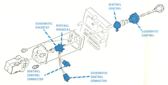
Delayed Exit
With the IGNITION SWITCH in Off or Lock, the SENTINEL CONTROL can be set to leave the headlights and exterior lights on for up to 4½ minutes. A variable timer in the AMPLIFIER automatically shuts off the lights after time expires.
TROUBLESHOOTING
TWILIGHT SENTINEL DOESN'T WORK
- Turn on PARKING LIGHTS to check fuse.
- Check AMPLIFIER ground connection through SENTINEL CONTROL SWITCH (terminal L) and LIGHT SWITCH (terminal B).
- Check voltage at AMPLIFIER.
- Check PHOTOCELL resistance.
- Check SENTINEL CONTROL resistance.
- Check AMPLIFIER output voltages (terminals F and H).
COMPONENT LOCATION
| Page/Figure | ||
| Photocell | Under left front speaker grille | 11-2 |
| Sentinel Amplifier | Behind left dash | 11-2 |
C109 |
Dash harness, near light switch |
11-2 |
12 - Front park / Cornering lights |
Back to the top |
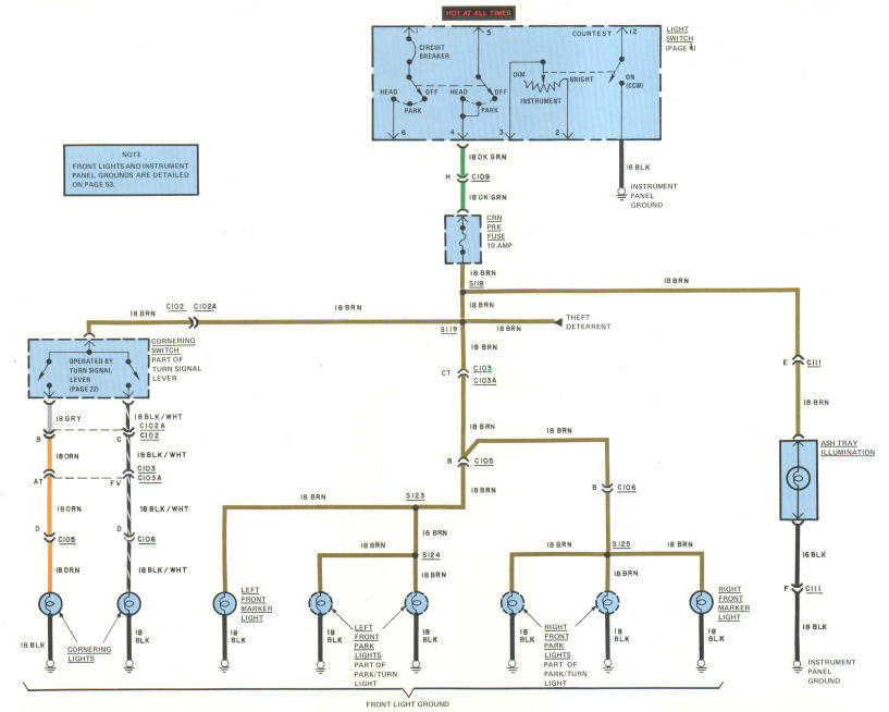
CIRCUIT OPERATION
With the LIGHT SWITCH pulled out to the first or second detent, current flows through the CRN PRK fuse to operate the PARK, MARKER, and CORNERING LIGHTS. All these lights are wired in parallel.
TROUBLESHOOTING
GROUP OF LIGHTS OUT
- Watch ASH TRAY ILLUMINATION to check fuse.
- Check for voltage at BULKHEAD CONNECTOR (C103A, terminal CT).
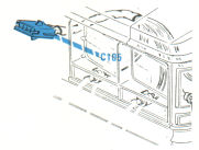
- Check for voltage at C105/C106, terminal B.
- Check for open ground (Ground Page).
SINGLE LIGHT OUT
- Check light socket connections.
- Check for open ground.
- Check for broken wire.
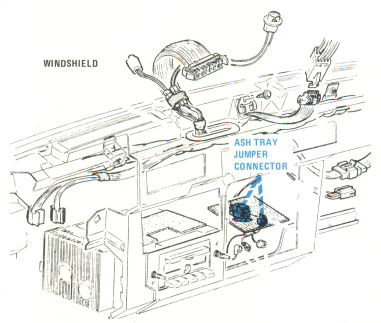
COMPONENT LOCATION
| Page/Figure | ||
| C103 | Behind fuse block | 12-1 |
| C103A | LH side of firewall | 12-1 |
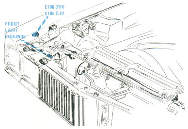
| C105 | LH front fender | 12-1 |
| C106 | RH front fender | 12-4 |
| C109 | Dash harness, near light switch | 12-2 |
13 - Rear park / Marker / License / Backup lights |
Back to the top |
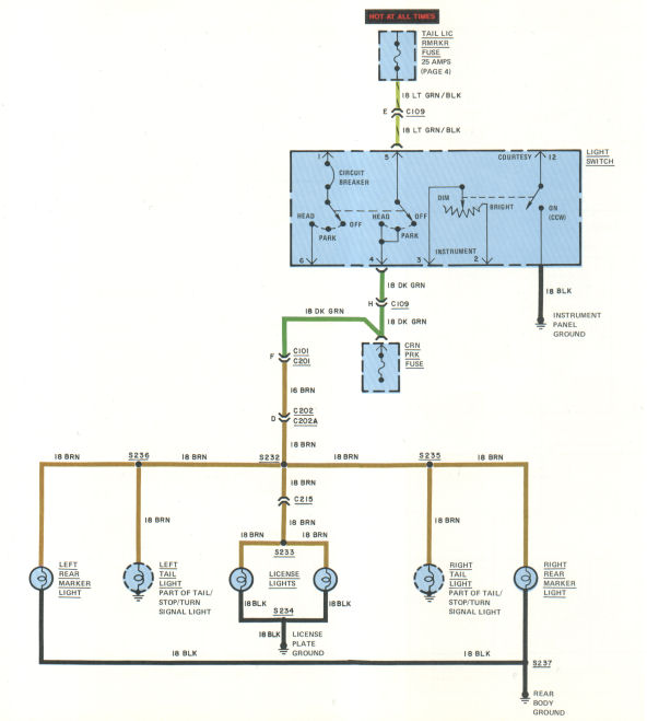
TROUBLESHOOTING
GROUP OF LIGHTS OUT
- Check voltage at CRN PRK FUSE (RH terminal).
- Check rear body ground or LICENSE PLATE ground.
- Check for circuit continuity.
SINGLE LIGHT OUT
- Check bulb.
- Check bulb socket connection.
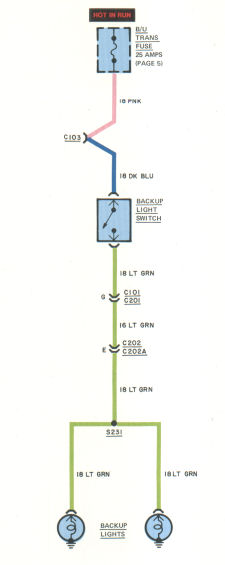
BACKUP LIGHTS DON'T WORK
- Operate ILLUMINATED ENTRY or SUNROOF to check fuse.
- Jiggle gear selector lever to check the backup switch linkage.
- Check power and ground connections at BACKUP SWITCH. Check for voltage at BACKUP SWITCH.
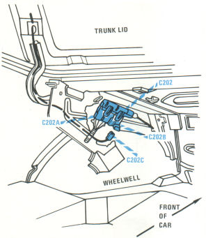
COMPONENT LOCATION
| Page/Figure | ||
| Rear Body Ground | Trunk lid striker plate | |
| License Light Ground | Trunk lid | |
C101 |
Fuse block dash wiring |
13-1 |
| C103 | Bulkhead | 5-1 |
| C109 | Under left dash | 12-2 |
| C201 | Fuse panel dash wiring | 13-1 |
| C202 | Rear body harness | 13-2 |
| C202B | Rear body harness | 13-2 |
| C215 | Near striker plate |
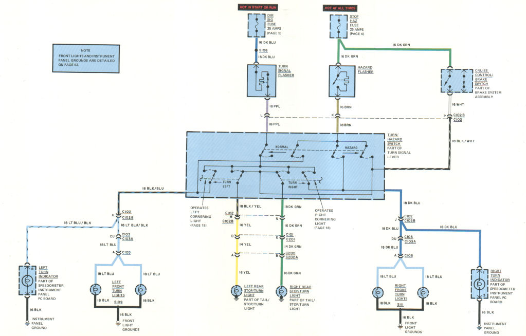
14 - Turn / Hazard / Stop lights |
Back to the top |
TROUBLESHOOTING
NO TURN SIGNALS
- Check DIR SIG FUSE.
- Check connections at flasher socket.
- Check connection of TURN SIGNAL CONNECTOR, C102, and FUSE PANEL CONNECTOR C101.
- Replace TURN SIGNAL FLASHER.
NO RIGHT FRONT TURN SIGNALS
- Check voltage at TURN LIGHT (C 106, terminal A, LT BLU wire).
- Connect TURN LIGHT (BLK wire) to ground and observe lights (see front light ground, Ground Page).
- Change both right front turn signal bulbs.
TURN SIGNALS FLASH ON ONE SIDE ONLY
- Check for burned-out bulbs.
- Check continuity through switch.
- Check continuity through turn/hazard switch.
- Check for bad ground.
NO HAZARD LIGHTS
- Operate STOP LIGHTS to check STOP HAZ FUSE.
- Check HAZARD FLASHER connections.
- Replace HAZARD FLASHER.
NO STOP LIGHTS
- Operate HAZARD FLASHER to check the STOP/HAZ FUSE.
- Check for continuity through STOP LIGHT SWITCH.
- Check voltage to STOPLIGHTS at TURN SIGNAL connector (C101, terminals B and E, YEL and DK GRN wires). D and E, YEL and DK GRN wires).
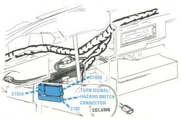
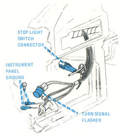
COMPONENT LOCATION
| Page/Figure | ||
| Stoplight Switch | Brake pedal support | 14-2 |
| Turn Signal Flasher | Dash harness near LH side panel | 14-2 |
C101 |
Fuse block |
5-1 |
| C102 | Steering column | 14-1 |
| C102B | Steering column | 14-1 |
| C103 | Bulkhead, behind fuse block | 5-1 |
| C103A | Bulkhead, front lights harness | 5-1 |
| C105 | Front left fender | 12-1 |
| C106 | Front right fender | 12-4 |
| C201 | Fuse block | 5-1 |
| C202 | Rear body harness | 13-2 |
| C202A | Rear body harness | 13-2 |
15 - Courtesy / Reading / Trunk / Dome / Glovebox lights / Cigar lighter / Clock / Illuminated entry |
Back to the top |
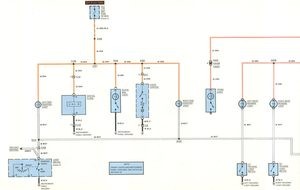
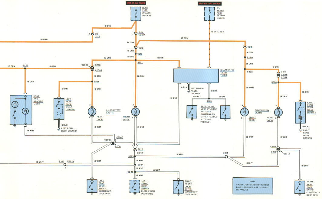
CIRCUIT OPERATION
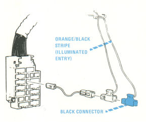
Illuminated Entry
The ILLUMINATED ENTRY TIMER is powered through the BODY FUSE when either FRONT DOOR LOCK CYLINDER SWITCH closes. All of the inside courtesy lights turn on and automatically turn off after about 20 seconds. The outside DOOR LOCK CYLINDERS are also illuminated by a fiber optic circuit routed from the front door courtesy light. If the IGNITION SWITCH is turned on before the 20 second period elapses, voltage is applied through the B/U TRANS FUSE to the ILLUMINATED ENTRY TIMER and the TIMER re-sets. The COURTESY LIGHTS turn off immediately.
TROUBLESHOOTING
ILLUMINATED ENTRY DOESN'T WORK
- Operate BACKUP LIGHTS to check B/U TRANS FUSE.
- Operate COURTESY LIGHTS to cheek BODY FUSE.
- Check ILLUMINATED ENTRY TIMER connections. Check voltage at ILLUMINATED ENTRY TIMER.
GROUP OF COURTESY LIGHTS DOESN'T WORK
- Operate REAR DOOR CIGAR LIGHTERS to check BODY FUSE.
- Check voltage at FUSE BLOCK CONNECTOR C201A (terminal L).
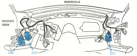
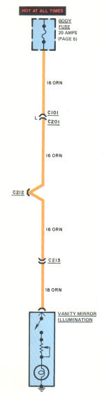
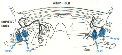
- Check voltages at BODY CONNECTORS C212 and C213 (ORN wires).
- Connect BODY CONNECTORS C212 and C213 (WHT wires) to ground and observe COURTESY LIGHTS.
DIGITAL CLOCK DOESN'T WORK
- Turn LIGHT SWITCH knob counter-clockwise and observe SIDE PANEL COURTESY LIGHTS. This checks CLK LTR ANT FUSE.
- Measure voltage at DIGITAL CLOCK connector (C110, terminal H, ORN wire)
- Connect wire from DIGITAL CLOCK connector (C110, terminal F, BLK wire) to ground and observe CLOCK.
COMPONENT LOCATION
| Page/Figure | ||
| Illuminated Entry Timer | Under left dash | |
| Illuminated Lock Cylinder | Front doors | |
| Right Reading Light Ground | Right rear upper quarter panel | |
| Left Reading Light Ground | Left rear upper quarter panel | |
C101 |
Fuse block |
5-1 |
| C109 | Dash harness, near light switch | 12-2 |
| C110 | Dash harness, near radio | 17-2 |
| C111 | Dash harness, near ash tray | 10-1 |
| C201 | Fuse panel | 18-1 |
| C201A | Fuse panel | 18-1 |
| C202 | Rear body harness | 13-2 |
| C202B | Rear body harness | 13-2 |
| C202C | Rear body harness | 13-2 |
| C208 | LH body harness | |
| C208A | LH body harness | |
| C208B | LH body harness | |
| C211 | RH body harness | |
| C211A | RH body harness | |
| C211B | RH body harness | |
| C212 | Cross body harness | 18-2 |
| C213 | Cross body harness | 18-2 |
16 - Rear grid defogger |
Back to the top |
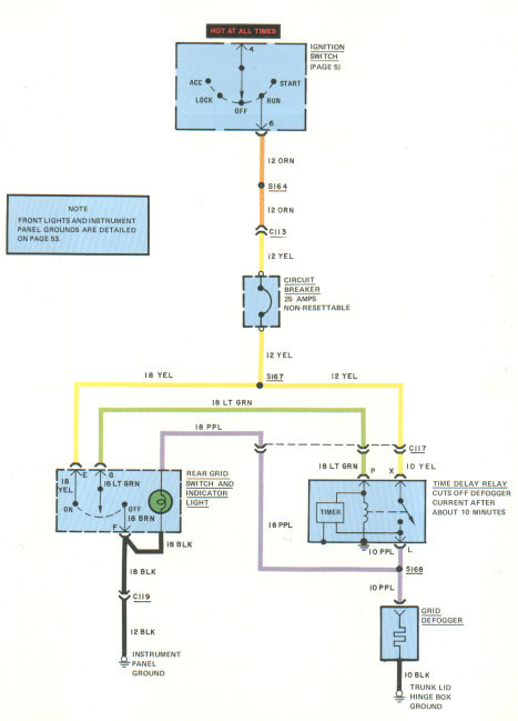
CIRCUIT OPERATION
When the REAR DEFOG SWITCH is pressed On (momentary), current passes through the LT GRN wire and energizes the relay coil. Current flows through the YEL wire, through tile closed contact of the relay, through the TIMER to ground (keeps the relay energized), and to the grid defogger. The indicator lights.
As soon as current flows through the TIMER, it begins a countdown (about 20 minutes). After about 20 minutes, the TIMER interrupts current to the relay coil, opening the relay contact and cutting off power to the grid defogger. The indicator light goes out.
If the DEFOG SWITCH is pressed to Off (momentary), the relay coil is grounded through the LT GRN wire. The relay coil is de-energized and power to the GRID DEFOGGER is cut off.
TROUBLESHOOTING
HEATER DOESN'T WORK
- Check circuit breaker connections. Check continuity through circuit breaker.
- Check switching of voltage to TIMER at C117 (LT GRN wire) when switch is pressed On and Off (TIMER input).
- Check switching of voltage at TIMER output (terminal L or C117, PPL wire).
INDICATOR LIGHT IS ON BUT NOT HEATER
- Check for voltage at GRID DEFOGGER connector (PPL wire).
HEATER GRID LINES OPEN
- Perform grid line tests per Cadillac Service Manual.
COMPONENT LOCATION
| Page/Figure | ||
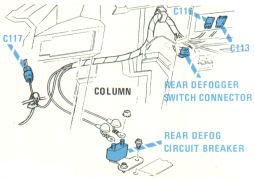
| Rear Defog Circuit Breaker | Under steering column | 16-1 |
| Time Delay Relay | Center dash wiring harness | |
C113 |
Center dash wiring harness |
16-1 |
| C116 | Center dash wiring harness | 16-1 |
| C117 | Fuse panel dash wiring | 16-1 |
17 - Instrument panel illumination |
Back to the top |
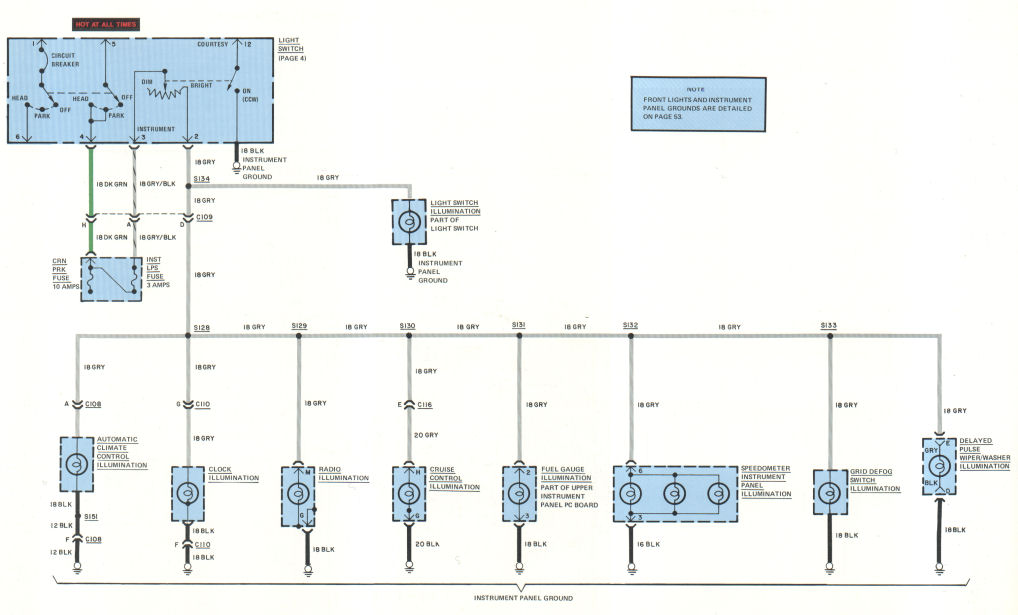
TROUBLESHOOTING
GROUP OF LIGHTS IS OUT
- Operate REAR PARK MARKER and LICENSE LIGHTS to check TAIL LIC RMRKR FUSE.
- Check voltage at LIGHT SWITCH connector (C109, terminal D, GRN wire).
- Check for open ground.
SINGLE LIGHT IS OUT
- Check bulb.
- Check bulb socket for broken wires and loose connections.

COMPONENT LOCATION
| Page/Figure | ||
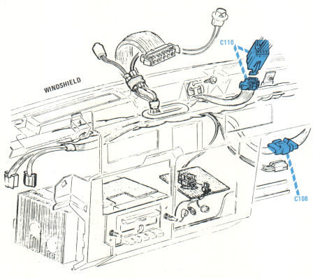
| C108 | Center dash harness | 17-2 |
| C109 | Dash harness, near headlight switch | 12-2 |
| C110 | Center dash harness | 17-2 |
18 - Warning / Vanity lights / Trunk release |
Back to the top |
TROUBLESHOOTING
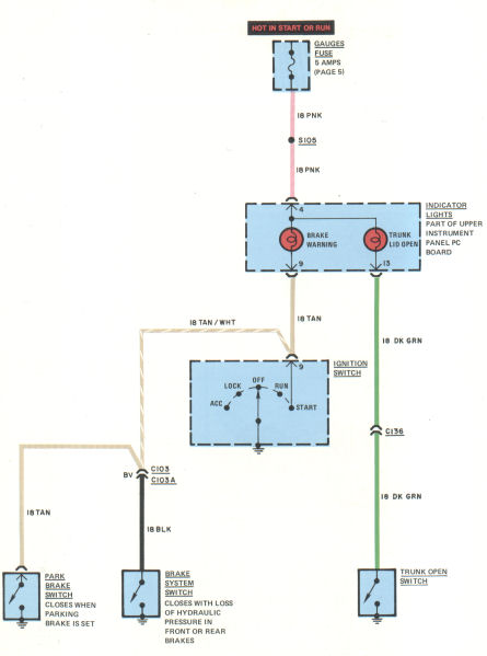
BRAKE WARNING LIGHT STAYS ON
- Check PARKING BRAKE is released.
WARNING: If car must be moved, drive with extreme caution, or tow. Do not drive long distances without having system repaired.
VANITY MIRROR LIGHT DOESN'T WORK
- Check for voltage at C213 (ORN wire) by opening any door and observing COURTESY LIGHTS.
- Check VANITY MIRROR SWITCH.
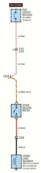
REMOTE CONTROL TRUNK LOCK DOESN'T WORK
- Check the TRUNK RELEASE SWITCH.
- Check voltage at the TRUNK LOCK SOLENOID (connector C216 BLK wire).
COMPONENT LOCATION
| Page/Figure | ||
| Brake System Switch | Brake combination valve mounted on left frame | |
| Trunk Lock Solenoid | Trunk latch | |
| Trunk Open Switch | Part of trunk closing unit | |
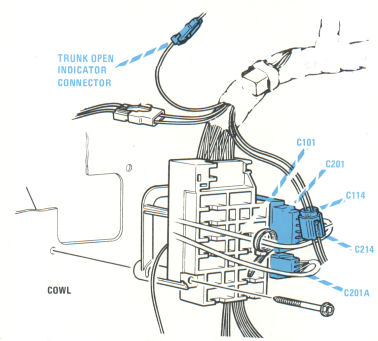
C101 |
Fuse block |
18-1 |
| C103 | Bulkhead, behind fuse block | 5-1 |
| C103A | Bulkhead, front lights harness | 5-1 |
| C114 | Dash harness near fuse block | 18-1 |
| C136 | Dash harness fuse block | |
| C201 | Fuse block | 18-1 |
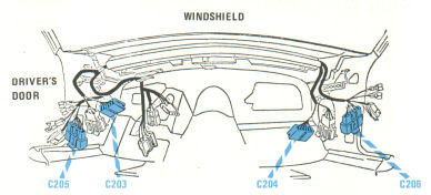
| C205 | Cross body harness | 18-2 |
| C212 | Left side body harness | 18-2 |
| C213 | Right side body harness | 18-2 |
| C214 | Dash harness near fuse block | 18-1 |
| C216 | Trunk lock solenoid |
19 - Delayed pulse wiper / Washer |
Back to the top |
CIRCUIT OPERATION
Wiper Operation
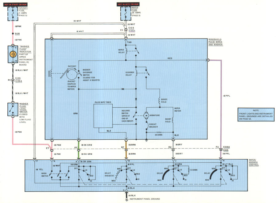
With the IGNITION SWITCH in Acc or Run, voltage is applied through the WIPER FUSE to the WIPER RELAY COIL. When the WIPER/WASHER CONTROL is turned to either Lo, Med, or Hi, the WIPER RELAY contacts close, and voltage is applied to the GEAR BOX RELAY. The GEAR BOX RELAY contacts close, and current flows through the WIPER MOTOR. The WIPER operates at the selected speed.
For Lo speed, the WIPER/WASHER CONTROL switches 0 ohms in series with the shunt field of the WIPER MOTOR.
For Med speed, the 13 ohm resistor is switched in parallel with 20 ohms, providing slightly less than 8 ohms in series with the shunt field. More current is forced through the series winding. The WIPER MOTOR speed increases.
For Hi speed, the 20 ohm resistor is connected with the shunt field, and more current is forced through the series winding. The motor runs at the highest speed.
To turn the wiper off, the WIPER/ WASHER CONTROL is turned Off. Current through the WIPER RELAY coil is interrupted, but the contacts remain closed. The WIPER MOTOR continues to run. When the wipers reach Park position, the WIPER RELAY contacts are mechanically opened by the cam. Current to the GEAR BOX RELAY and the WIPER MOTOR is then interrupted.
Pulse Operation
For controlled Delay between wiper sweeps, the WIPER/WASHER CONTROL is switched down and to the right. Current is sent to the PULSE WIPER TIMER through the DELAY RHEOSTAT. By adjusting the RHEOSTAT, the time between sweeps can be varied from 0 seconds up to Max of about 12 seconds.
The WIPER RELAY is energized, sending current to the GEAR BOX RELAY. When the set time is up, the PULSE WIPE TIMER switches the GEAR BOX RELAY to ground, closing the contacts. The wiper sweeps once. The HOLDING SWITCH closes, resetting the TIMER. At the end of the wiper sweep, the HOLDING SWITCH opens, and the timer begins to time out again.
The delayed wipe is turned Off by turning the WIPER/WASHER CONTROL Off. Current to the WIPER RELAY is interrupted. The WIPER completes one final sweep. At the end of the sweep, the HOLDING SWITCH opens, interrupting current to the GEAR BOX RELAY.
Washer Operation
The WINDSHIELD WASHER is turned on by depressing the WASH SWITCH. Current is sent to the WASHER OVERRIDE SWITCH, the WIPER RELAY, and the GEAR BOX RELAY. The washer squirts about 8 times while the wipers sweep about 4 times in Lo speed. After the washer completes the squirts, the wipers sweep 2 additional times and automatically turn off.
If the WIPER/WASHER CONTROL is turned on to Lo, Med, or Hi when the WASH SWITCH is pressed, the WASHER operates as usual but the wipers run at the set speed. If the WIPER/WASHER CONTROL is switched to controlled Delay, pressing the WASH SWITCH closes the WASHER OVERRIDE SWITCH. This causes override of the delayed cycle. Following completion of the wash, the delayed cycle is resumed.
TROUBLESHOOTING
WIPER DOESN'T WORK
- Check WIPER FUSE.
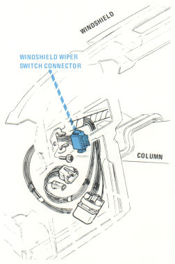
- Check for power at WINDSHIELD PULSE WIPER and WASHER UNIT between TAN and BLK wires of the 3-terminal connector (WIPER/WASHER CONTROL in Lo).
- Ground the GRY wire at WIPER WASHER CONTROL (terminal J). If wiper works, replace switch; if not, replace WINDSHIELD PULSE WIPE and WASHER unit.
CONTROLLED DELAY DOESN'T WORK
- Check DELAY RHEOSTAT.
WASHER DOESN'T WORK
- Ground the PNK wire at WIPER/WASHER CONTROL (terminal G). If washer works, replace switch; if not, replace WINDSHIELD PULSE WIPE and WASHER unit.
COMPONENT LOCATION
| Page/Figure | ||
| C103 | Bulkhead, behind fuse block | 5-1 |
| C103A | Bulkhead, front lights harness | 5-1 |
20 - Power windows |
Back to the top |
TROUBLESHOOTING
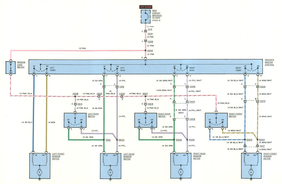
NO WINDOWS WORK
- Operate REMOTE CONTROL TRUNK LOCK.
- Check WDO CIRCUIT BREAKER.
- Check voltage at DRIVER'S MASTER CONTROL (terminal E, PNK wire).
- Push left front toggle to Dn. Check voltage at DRIVER'S MASTER CONTROL (terminal H, BRN wire).
ONE WINDOW DOESN'T WORK
- Check continuity through WINDOW LOCK SWITCH.
- Check voltage and ground connections at WINDOW MOTOR.
COMPONENT LOCATION
| Page/Figure | ||
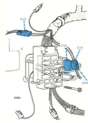
| C114 | Dash harness near fuse block | 5-1 |
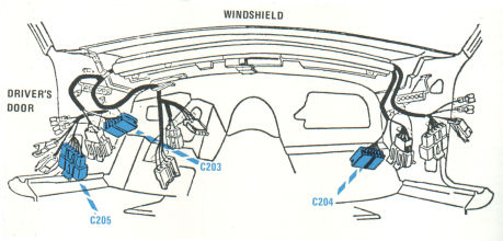
| C203 | Cross body harness | 20-2 |
| C204 | Cross body harness | 20-2 |
| C205 | Cross body harness | 20-2 |
| C209 | Right body harness | |
| C210 | Left body harness | |
| C214 | Dash harness near fuse block | 20-1 |
| C217 | Right front motor |
21 - Power seats (6 way) |
Back to the top |
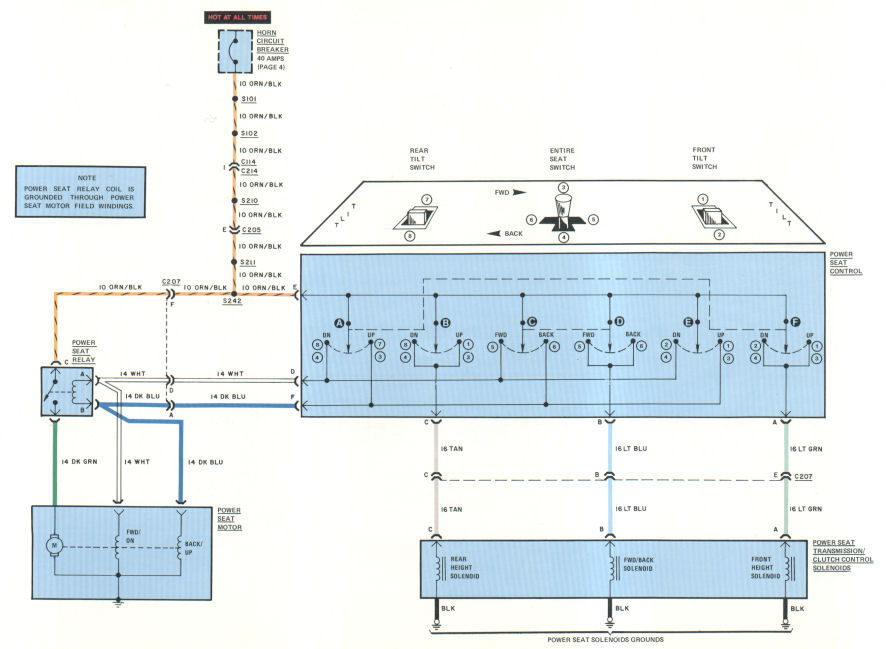
CIRCUIT OPERATION
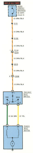
The drive unit in the SIX-WAY POWER SEATS is an electric motor controlled by a transmission. Three solenoids inside the transmission operate clutches to drive the seat fwd/back, front up/dn, or rear up/dn.
The numbers on the diagram above the POWER SEAT CONTROL match the numbers inside the CONTROL. These numbers show what switch closes when the POWER SEAT CONTROL is moved in each direction. For example: closing switch 3 (entire seat up) allows current flow from the circuit breaker through sections A and E (UP side). Current flows out of the SEAT CONTROL at terminal F, energizing the POWER SEAT RELAY coil (through terminal B), and through the DK BLU wire energizing the BACK/UP winding of the MOTOR, and on to ground. The RELAY coil is grounded at the same time through the WHT wire and FWD/DN winding of the MOTOR. Switch 3 also closes sections B and F, energizing the FRONT and REAR HEIGHT SOLENOIDS to drive the entire seat up.
TROUBLESHOOTING
NO SEAT CONTROLS WORK
- Sound HORNS to check circuit breaker.
- Check voltage at POWER SEAT SWITCH (terminal E, ORN/BLK wire).
- Push control toggle to Fwd. Check for voltage at POWER SEAT SWITCH (terminals D and B).
- Connect POWER SEAT RELAY (terminal B), to ground. Check for operation of POWER SEAT MOTOR.
- Check POWER SEAT SOLENOID grounds.
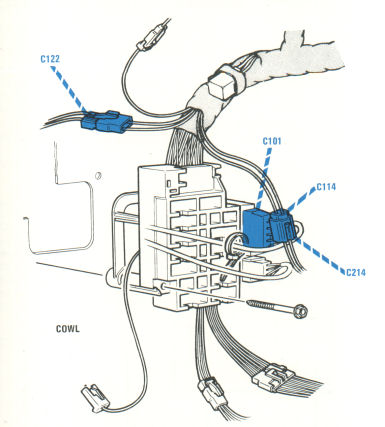
COMPONENT LOCATION
| Page/Figure | ||
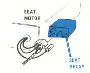
| Power Seat Motor | Left side of front seat | 21-2 |
| Power Seat Relay | Mounted on power seat motor | 21-2 |
C114 |
Dash harness near fuse block |
21-1 |
| C205 | Cross body harness | 22-2 |
| C207 | Cross body harness | |
| C214 | Dash harness near fuse block | 20-1 |
22 - Power seats (2 way) / Door locks |
Back to the top |
CIRCUIT OPERATION
Two-Way Seat
The POWER SEAT MOTOR has two windings.
Current flows through one winding to move the seat forward, and the other winding to move the seat back.
The two-way switch sends current to the FWD or BACK winding.
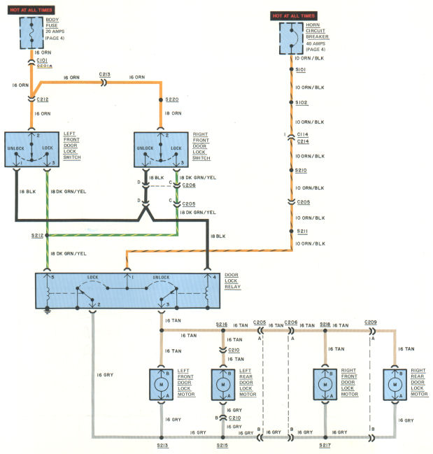
Power Door Locks
When either door lock switch is pressed to Lock, current flows through the DK GRN/YEL wire to the DOOR LOCK RELAY. When the LOCK RELAY is energized, current flows from the ORN/BLK wire, through the relay contacts, through the GRY wire, through the lock motors, through the TAN wire, and to ground through the UNLOCK side of the DOOR LOCK RELAY.
NOTE: Current flows through the motor in one direction to lock, and the opposite direction to unlock.
In the "at rest" position, the LOCK and UNLOCK contacts of the relay are both grounded.
TROUBLESHOOTING
SEAT DOES NOT WORK
- Operate HORN to check circuit breaker.
- Check connections at the TWO-WAY SEAT SW1TCH.
- Check voltage at the TWO-WAY SEAT SWITCH (terminal 1, ORN/BLK wire).
- Check POWER SEAT MOTOR ground.
- Check input voltages to POWER SEAT MOTOR (DK GRN or YEL wire).
NO LOCKS WORK
- Sound the HORN to check circuit breaker. Open doors and observe COURTESY LIGHTS to check fuses.
- Check connections to POWER LOCK RELAY.
ONE LOCK DOES NOT WORK
- Check continuity of faulty lock motor circuit.
COMPONENT LOCATION
| Page/Figure | ||
| Door Lock Motor | In doors | |
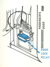
| Door Lock Relay | Base of RH "A" pillar | 22-1 |
C101 |
Dash harness near fuse block |
5-1 |
| C114 | Dash harness near fuse block | 5-1 |
| C201A | Dash harness near fuse block | 5-1 |
| C205 | Cross body harness | 22-2 |
| C206 | Cross body harness | 22-2 |
| C209 | Right side body harness | |
| C210 | Left side body harness | |
| C212 | Left side body harness | 22-2 |
| C213 | Right side body harness | 22-2 |
| C214 | Dash harness near fuse block | 20-1 |
23 - Theft deterrent |
Back to the top |
CIRCUIT OPERATION
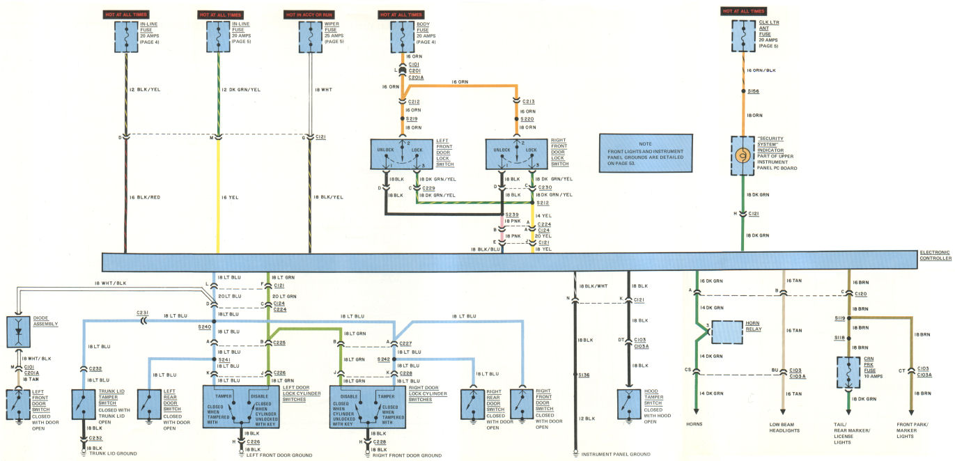
Arming the Security System
The SECURITY SYSTEM is armed by pressing a DOOR LOCK SWITCH to Lock. BATTERY voltage from the BODY FUSE is connected through the DOOR LOCK SWITCH to the ELECTRONIC CONTROLLER and enables the THEFT DETERRENT. The flashing signal from the ELECTRONIC CONTROLLER stops, and the INDICATOR glows continuously. When all the doors are closed, the DOOR JAMB SWITCHES are open and current to the INDICATOR is cut off. The SECURITY SYSTEM is armed.
Setting Off the Alarm
The SECURITY ALARM is set off when the DOOR LOCK CYLINDERS or the TRUNK LOCK CYLINDER is tampered with. Forcing the hood to the "Safety" position also sets off the alarm.
Tampering with any door lock cylinder, the trunk lock cylinder, or hood causes a TAMPER SWITCH to close. (The TRUNK can be opened with the key without closing the TAMPER SWITCH.) This grounds the ELECTRONIC CONTROLLER and activates the alarm signals. Current through one IN-LINE FUSE is pulsed to the horns by the ELECTRONIC CONTROLLER. Current through the other IN-LINE FUSE is pulsed to the LOW BEAM HEADLIGHTS and the PARKING, MARKER, TAIL, and LICENSE LIGHTS. The horns and lights are actuated at about 50 pulses per minute.
The alarm operates for 3 to 7 minutes. After shutting off, the SECURITY SYSTEM is automatically re-armed, unless a lock is damaged.
Disarming the Security System
Unlocking the door with a key disarms the system. The DISABLE SWITCH is closed, grounding the ELECTRONIC CONTROLLER. The CONTROLLER is reset, disabling the SECURITY SYSTEM. Turning the IGNITION SWITCH On connects battery voltage to the CONTROLLER through the WIPER FUSE. This also disarms the SECURITY SYSTEM.
When the alarm is set off, it can only be shut off by unlocking the door with the key. The DISABLE SWITCH closes, grounding the ELECTRONIC CONTROLLER. The CONTROLLER re-sets, and the alarm shuts off.
If a lock is damaged, the TAMPER SWITCH closes. With the IGNITION SWITCH Off, the ELECTRONIC CONTROLLER flashes the INDICATOR, warning the SECURITY SYSTEM is activated. With the IGNITION SWITCH to Acc or Run, the CONTROLLER turns the INDICATOR off. With the IGNITION Off, the INDICATOR continues to flash.
TROUBLESHOOTING
SECURITY SYSTEM INDICATOR FLASHES CONTINUALLY WITH IGNITION OFF (LIGHT GOES OUT WITH IGNITION ON)
- Inspect car for theft and lock damage.
- Check for faulty TAMPER SWITCH (failed closed).
- Repair or replace damaged switch.
SECURITY SYSTEM WILL NOT ARM
- Operate POWER DOOR LOCKS to check DOOR LOCK SWITCHES.
- Test for operation of COURTESY LIGHTS and CIGAR LIGHTERS to check BODY FUSE.
COMPONENT LOCATION
| Page/Figure | ||
| Electronic Controller | Behind instrument panel, to right of glove box | |
| Hood Switch | Right of hood lock plate | |
| In-Line Fuses | Above glove box liner | |
C101 |
Fuse block |
5-1 |
| C103 | Bulkhead, behind fuse block | 5-1 |
| C103A | Bulkhead, front lights harness | 5-1 |
| C120 | Right upper dash | |
| C121 | Right upper dash | |
| C212 | Left side body harness | 18-2 |
| C213 | Right side body harness | 18-2 |
| C124 | Power door locks and theft deterrent harness | |
| C201A | Fuse block | 5-1 |
| C224 | Power door locks and theft deterrent harness | |
| C224 | Power door locks and theft deterrent harness | |
| C225 | Left front door theft alarm harness | |
| C226 | Left door lock cylinder | |
| C227 | Right front door theft alarm harness | |
| C228 | Right door lock cylinder | |
| C229 | Left front door lock harness | |
| C230 | Right front door lock harness | |
| C231 | Trunk | |
| C232 | Trunk lock cylinder |
24 - Cruise control |
Back to the top |
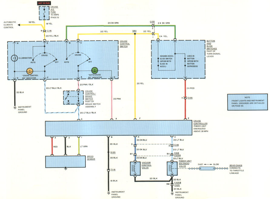
CIRCUIT OPERATION
NOTE: CRUISE CONTROL operates only when car is going 30 mph or faster.
Cruise Mode
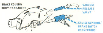
With the CRUISE CONTROL SWITCH in Cruise, current flows to the CRUISE CONTROLLER through the LT BLU/BLK wire. The amber "CRUISE CONTROL ON" INDICATOR lights. Current flows through the CRUISE CONTROL BRAKE SWITCH, through the YEL wire to terminal F of the CRUISE CONTROLLER and terminal 1 of the BUTTON and SLIDE SWITCHES, and on to terminal E of the CRUISE CONTROLLER The cruise speed is ready to be set.
Cruise speed is set by interrupting current to terminal E of the CRUISE CONTROLLER (momentarily opening LOCK-IN BUTTON). When the cruise speed is set, the green "AUTO/CRUISE ON" INDICATOR lights. The SPEED SENSOR sends signals to the CONTROLLER telling car speed. The CONTROLLER then matches the car speed to the set cruise speed The throttle position is varied through the electrical and vacuum connections.
The cruise speed is reduced by holding the LOCK-IN BUTTON depressed. Car speed slows as long as the BUTTON is held in. Releasing the LOCK-IN BUTTON sets a new cruise speed.
The CRUISE CONTROL shuts off and cruise speed is canceled:
1. if the brake pedal is depressed;
2. if the CRUISE CONTROL SWITCH is turned Off;
3. if the IGNITION SWITCH is turned Off;
4. if the car speed falls below approximately 30 mph.
Auto Mode
With the CRUISE CONTROL switch in Auto, current flows to the CRUISE CONTROLLER through the LT BLU/BLK wire. The amber "CRUISE CONTROL ON" INDICATOR lights. Current flows through the CRUISE CONTROL BRAKE SWITCH, through the DK GRN wire, and to the CRUISE CONTROLLER terminals E (through the RED wire) and F (through the YEL wire). The auto/cruise speed is ready to be set.
Auto/cruise speed is set by interrupting current to terminal E of the CRUISE CONTROLLER (momentarily opening the LOCK-IN BUTTON). When auto/cruise speed is set, the green "AUTO/CRUISE ON" INDICATOR lights. The speed sensor sends signals to the CONTROLLER telling car speed. The CONTROLLER then matches the car speed to the set cruise speed. The throttle position is varied through the electrical and vacuum connections.
The cruise speed is increased by holding the SLIDE SWITCH depressed. Car speed increases at a gradual rate until the SLIDE SWITCH is released. Releasing the SLIDE SWITCH sets a new cruise speed.
Depressing the brake pedal does not cancel the cruise speed in Auto Mode. When car speed drops below 30 mph, the "AUTO/ CRUISE ON" INDICATOR goes out, but the memory stores the cruise speed. When the car speed goes above 30 mph, the SLIDE SWITCH can be momentarily depressed, and the Auto Mode re-activated. The "AUTO/CRUISE ON" INDICATOR lights, and car speed gradually increases up to the pre-set cruise speed.
The AUTO CRUISE CONTROL shuts off, and cruise speed memory is cancelled:
1. if the CRUISE CONTROL SWITCH IS turned Off;
2. if the IGNITION SWITCH is turned Off.
TROUBLESHOOTING
SPEED CONTROL DOESN'T WORK
- Operate AIR CONDITIONER to check A/C CRUISE FUSE.
- Check for input voltages at CRUISE CONTROLLER, terminals G, E, and F.
- Check for output voltages at CRUISE CONTROLLER, terminals C and H.
- Check vacuum and throttle cruise control linkage.
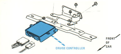
COMPONENT LOCATION
| Page/Figure | ||
| Cruise controller | Under dash | 24-1 |
| Power Unit Solenoid Valve | Top front engine | |
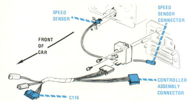
| Speed Sensor | Under dash | 24-2 |
| Vacuum Control Valve | Center firewall | |
C103 |
Bulkhead, behind fuse block |
5-1 |
| C103B | Bulkhead, engine harness | 5-1 |
| C116 | Under dash | 24-2 |
| C135 | Cruise control harness |
25 - Electronic leveling control |
Back to the top |
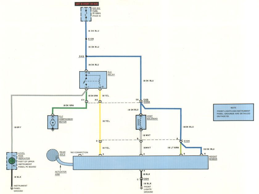
CIRCUIT OPERATION
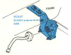
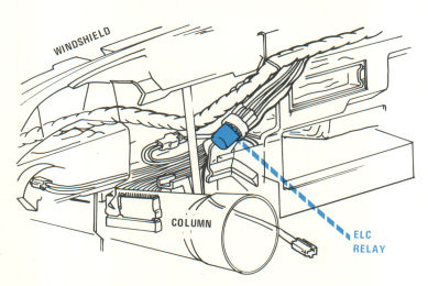
The HEIGHT SENSOR is connected to the rear axle by an actuating arm. The sensor detects the difference between what the height should be (pre-set value) and what the height is.
If the SENSOR detects more weight has been added (car too low), after a delay of about 12 seconds it grounds the ELC RELAY. Current flows through the closed contact of the ELC RELAY, powering the compressor and indicator light.
If the SENSOR detects weight has been removed (car too high), it grounds the vent solenoid. Current flows through the vent solenoid to ground, and the pneumatic system is vented.
When the height reaches the pre-set value, the SENSOR opens the ground circuits.
TROUBLESHOOTING
ELC WILL NOT WORK
- Check for voltage at ELC RELAY.
- Check for voltage at HEIGHT SENSOR (terminals 5 and 6, LT GRN and DK BLU wires).
- Check for voltage at COMPRESSOR MOTOR (DK GRN wire) or EXHAUST SOLENOID (DK BLU wire).
- Check for continuity to ground at HEIGHT SENSOR (terminals 2 and 3, YEL and WHT wires).
COMPONENT LOCATION
| Page/Figure | ||
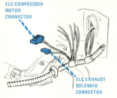
| Compressor Motor | Left front fenderwell (part of ELC compressor assembly) | 25-1 |
| ELC Relay | Dash harness, near steering column | 25-3 |
| Exhaust Solenoid | Left front fenderwell (part of ELC compressor assembly) | 25-1 |
| Height Sensor | Rear frame cross member | 25-2 |
C103 |
Bulkhead, behind fuse block |
5-1 |
| C103A | Bulkhead (connects to forward light harness) | 5-1 |
| C104 | Left engine compartment |
26 - Seatbelt chimes / Belt retractor / Oil pressure indicator / Sunroof |
Back to the top |
CIRCUIT OPERATION
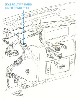
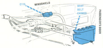
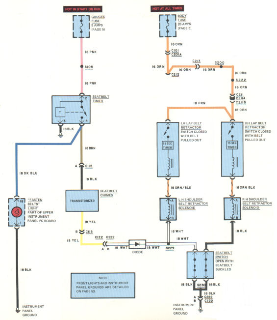
Seatbelt Chimes
With the seatbelt unbuckled, the "FASTEN BELTS" sign lights for 4 to 8 seconds, and the chimes sound for the same length of time.
With the seatbelt buckled, the "FASTEN BELTS" sign lights for 4 to 8 seconds.
Seatbelt Retractors
When the seatbelt is pulled out and buckled, the switch in the lap belt retractor is closed. The retractor solenoid in the belt housing is energized and the 15 second timer starts counting down. When the 15 seconds are up or when the seatbelt is buckled, current to the solenoid is interrupted. The interia reel locks.
When the seatbelt is unbuckled, the inertia reel is automatically unlocked.
TROUBLESHOOTING
LIGHT AND CHIMES DON'T WORK
- Observe PARKING BRAKE WARNING LIGHT to check fuse.
- Check TIMER connections
- Check voltage at TIMER.
SEATBELT CHIMES DON'T SOUND
- Check seatbelt switch continuity to ground.
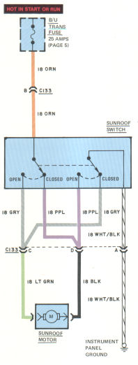
SUNROOF WON'T OPEN
- Shift transmission to reverse. Observe BACKUP LIGHTS to check B/U TRANS Fuse.
- Check connections at SUNROOF SWITCH:
-- C133 (terminal B, ORN wire) - Input Voltage
-- C133 (terminal C, LT GRN wire) - Motor Lead
-- C133 (terminal D, BLK wire) - Motor Lead
- Connect C133, terminal A (18 WHT/ BLK wire) to ground. Operate SUNROOF.
COMPONENT LOCATION
| Page/Figure | ||
| Lap Belt Retractor | Side floor panel | |
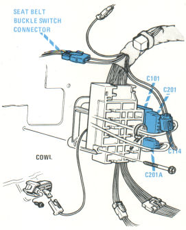
| Seatbelt Switch | Inner front seat | |
| Seatbelt Warning Chimes | Forward side of glove box liner | 26-2 |
| Shoulder Belt Retractor Solenoid | Dash harness, near transmission downshift switch | 26-1 |
| Shoulder Belt Retractor Solenoid | Quarter inner panel | |
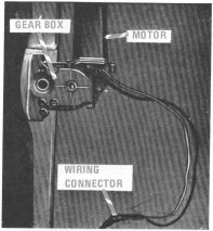
| Sunroof Motor | Center of windshield header area | 26-3 |
C101 |
Fuse block dash harness |
5-1 |
| C103 | Bulkhead, behind fuse block | 5-1 |
| C103A | Bulkhead, engine harness | 5-1 |
| C115 | RH dash wiring | 26-2 |
| C122 | Fuse block dash harness | 5-1 |
| C133 | Sunroof motor | 26-3 |
| C201A | Fuse panel dash harness | 5-1 |
| C211 | RH body harness | |
| C211B | RH body harness | |
| C213 | RH cross body harness | 18-2 |
| C222 | Fuse block dash harness |
27 - Radio / Power antenna |
Back to the top |
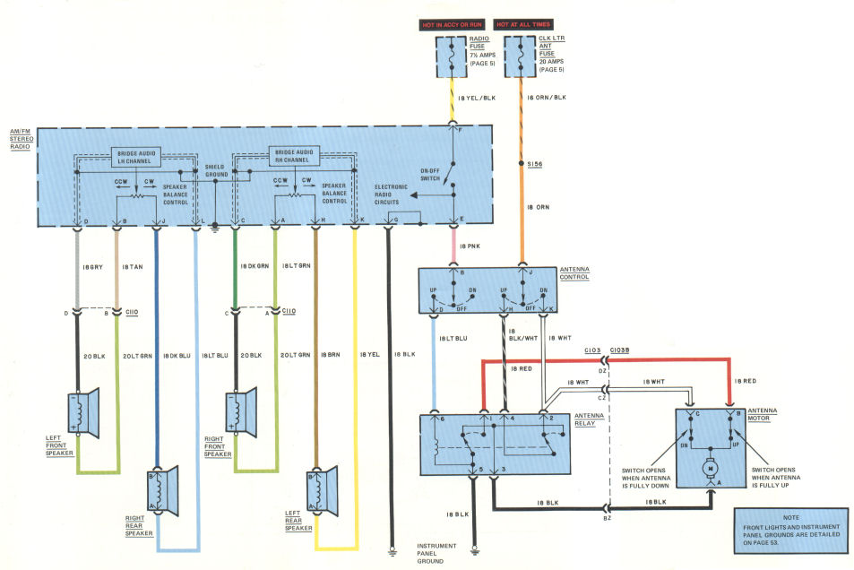
TROUBLESHOOTING
RADIO DOESN'T WORK
- Operate POWER ANTENNA to check voltage to RADIO.
- Connect RADIO (terminal G) to ground and operate RADIO.
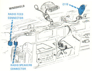
ONE SPEAKER DOESN'T WORK
- Check speaker connections (C110 for front speakers, A and B at rear speakers).
IGNITION NOISE
- Replace NOISE SUPPRESSION CAPACITOR (DISTRIBUTOR).
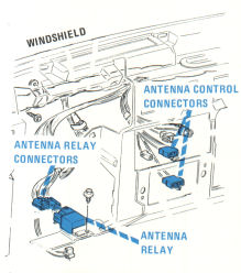
POWER ANTENNA DOESN'T WORK
- Operate RADIO to check RADIO FUSE.
- To check CLK LTR ANT FUSE, check to see if clock is running.
- With the ANTENNA CONTROL pushed to Up, check voltages at ANTENNA RELAY (terminals 6, 4, and 3).
- Connect ANTENNA RELAY (terminal 5) to ground and operate POWER ANTENNA.
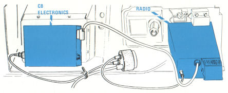
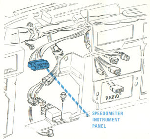
COMPONENT LOCATION
| Page/Figure | ||
| Antenna Relay | Dash harness, near speedometer instrument panel | 27-2 |
C103 |
Bulkhead, behind fuse block |
5-1 |
| C103B | Bulkhead, engine harness | 5-1 |
| C110 | Dash harness near radio | 27-1 |
28 - Automatic climate control |
Back to the top |
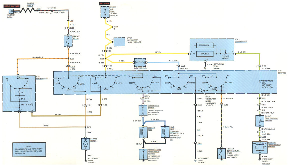
CIRCUIT OPERATION
The AUTOMATIC CLIMATE CONTROL is an electro-mechanical-vacuum system which maintains a set in-car temperature.
With the AUTOMATIC TEMPERATURE CONTROL in any position except Off, the PROGRAMMER AMPLIFIER senses the difference between the in-car temperature and the set temperature.
If the in-car temperature is warmer than the set temperature, the outside air is cooled as it enters the car (except in Econ). If the in-car air is cooler than the set temperature, the incoming air is warmed.
If the AMPLIFIER senses a big difference between the in-car air temperature and the set temperature, it commands the blower to work at high speed. As the difference between the two temperatures is reduced, the AMPLIFIER slows the BLOWER speed.
Electrical commands from the AMPLIFIER are changed into vacuum or mechanical movements by the TRANSDUCER.
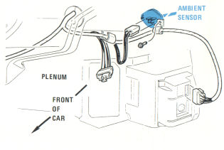
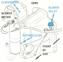
COMPONENT LOCATION
| Page/Figure | ||
| Ambient Temperature Sensor | Mounted on plenum surface | 28-1 |
| ATC Programmer | Under right side or instrument panel | |
| Blower Motor | Mounted on evaporator assembly, to right of cowl | 28-2 |
| Blower Relay | Mounted on evaporator assembly, to right of cowl | 28-2 |
| Clutch Coil | A/C compressor, front right of engine | |
| Compressor Switch (Thermostatic Cycling) | Mounted on evaporator case | |
| Heater Temperature Switch | Top front of engine | |
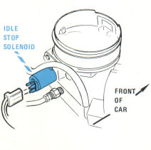
| Idle Stop Solenoid | Back of throttle assembly | 28-3 |
| In-car Temperature Sensor | Instrument panel cover | |
| Low Pressure Compressor Switch | Mounted on compressor | |
C103 |
Bulkhead, behind fuse block |
5-1 |
| C103B | Bulkhead, engine harness | 5-1 |
| C108 | Center dash wiring | 17-2 |
| C116 | Dash harness, near cruise controller | 16-1 |
| C125 | ATC control | |
| C126 | ATC control |
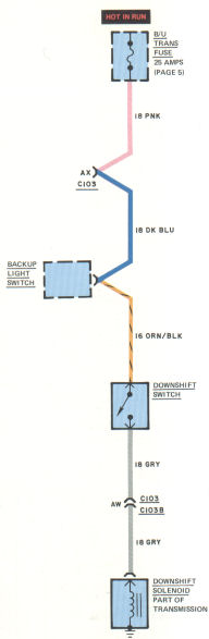
29 - Horn / Downshift solenoid |
Back to the top |
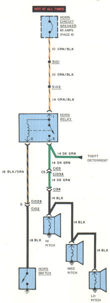
TROUBLESHOOTING
HORNS DON'T WORK
- Operate POWER DOOR LOCKS to check HORN CIRCUIT BREAKER.
- Check voltage at C134 (BLK wire).
ONE HORN DOESN'T WORK
- Check horn ground connection.
- Check voltage at horn connector.
COMPONENT LOCATION
| Page/Figure | ||
| Downshift Solenoid | Mounted above accelerator | |
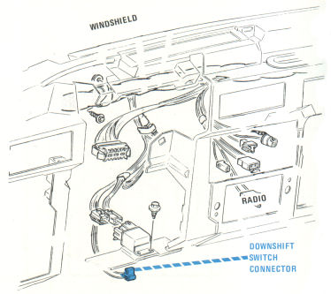
| Downshift Switch | Above accelerator | 29-1 |
| Horn Relay | Dash harness, near fuse block | |
| Horns | Right front fender | |
C102 |
Steering column |
14-1 |
| C103 | Bulkhead, behind fuse panel | 5-1 |
| C103B | Bulkhead, engine harness | 5-1 |
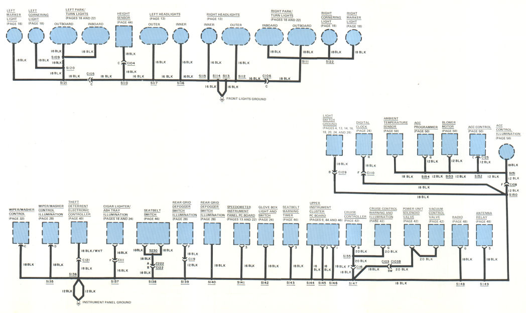
30 - Grounds |
Back to the top |
31 - Trunk pull down |
Back to the top |
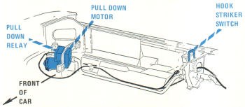
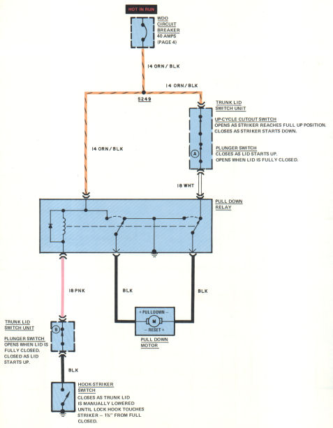
CIRCUIT OPERATION
Closing Cycle (Pull Down)
The HOOK-STRIKER SWITCH closes as the trunk lid is lowered. Current flows through the WDO CIRCUIT BREAKER and energizes the PULL DOWN RELAY. The PULL DOWN MOTOR runs until the PLUNGER SWITCH B opens.
Opening Cycle (Reset)
The TRUNK LID SWITCH UNIT PLUNGER SWITCH A closes as the trunk lid starts up. Current flows through the closed PULL DOWN RELAY contacts, operating the PULL DOWN MOTOR. Tile striker is driven to its full up position. As the striker reaches its full up position, the UP-CYCLE CUTOUT SWITCH opens, stopping the PULL DOWN MOTOR.
TROUBLESHOOTING
TRUNK PULL DOWN DOESN'T WORK
- Check PULL DOWN RELAY is grounded.
- Operate POWER WINDOWS to check WDO CIRCUIT BREAKER.
COMPONENT LOCATION
| Page/Figure | ||
| Trunk Lid Switch Unit | Part of striker pull down unit | |
| Pull Down Relay | Attached to pull down motor | 31-1 |
| Pull Down Motor | 31-1 | |
| Hook-Striker Switch | Part of striker pull down unit | 31-1 |

32 - Automatic door locks |
Back to the top |
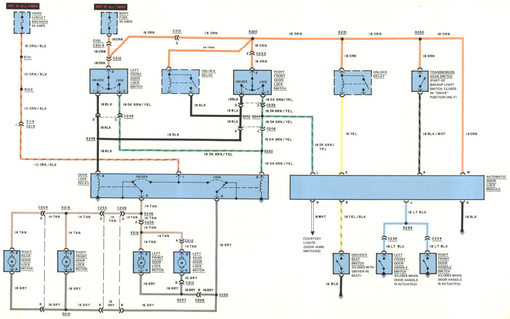
CIRCUIT OPERATION
Manual Locking
When either FRONT DOOR LOCK SWITCH is pressed to Lock, current flows through the DK BRN/YFL wire to the DOOR LOCK RELAY. After the DOOR LOCK RELAY is energized, current flows from the ORN/BLK wire, through the relay contacts, through the GRY wires, through the DOOR LOCK MOTORS, through tue FAN wires, and to ground through the UNLOCK side of the DOOR LOCK RELAY.
NOTE: Current flows through the motors in one direction to lock, and the opposite direction to unlock.
In the "at rest" position, the LOCK and UNLOCK contacts of the relay are both grounded.
Automatic Locking
When the transmission shift lever is in D, a voltage signal is sent through the TRANSMISSION GEAR SWITCH to the AUTOMATIC DOOR LOCK MODULE, terminal A. When the driver is seated, the DRIVER SEAT SWITCH closes and grounds terminal B. With the courtesy lights off and all the doors closed (all switches turned off), terminal N is ungrounded. With the driver seated, all the doors closed, and the shift lever in D, current flows through the ORN wire, to terminal M of the AUTOMATIC DOOR LOCK MODULE, from terminal L though the DK ORN/YEL wire to the DOOR LOCK RELAY. All of the doors are automatically locked.
When any door is opened (or the COURTESY LIGHTS turned on) with the driver seated and tile gear lever in D, terminal N on the AUTOMATIC DOOR LOCK MODULE is grounded. When the door is shut, terminal N is ungrounded and the door is automatically locked by the AUTOMATIC DOOR LOCK MODULE.
TROUBLESHOOTING
DOORS DON'T LOCK AUTOMATICALLY
- Actuate the DRIVER SEAT SWITCH. Shift the transmission gear lever to D. Check for voltage at the AUTOMATIC DOOR LOCK MODULE, terminals M and L.
DOORS WON'T UNLOCK BY ACTUATING FRONT DOOR HANDLE SWITCHES
- Lock the doors. Actuate the DRIVER SEAT SWITCH. Place the gear lever in P, R, or N. Ground the AUTOMATIC DOOR LOCK MODULE, terminal J and watch for unlocking of doors. Ground the UNLOCK RELAY (terminal with YEL wire) and watch for unlocking of doors.
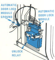

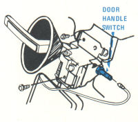
COMPONENT LOCATION
| Page/Figure | ||
| Automatic Door Lock Module | Right front shroud side panel | 32-1 |
| Door Handle Switch | Base of front door inside handle | 32-3 |
| Door Lock Motor | In doors | |
| Door Lock Relay | Base of RH "A" pillar | 32-2 |
| Driver Seat Switch | Driver's seat | |
| Transmission Gear Switch | Part of backup light switch | |
| Unlock Relay | Right front shroud side panel, taped to automatic door lock module | 32-1 |
C101 |
Dash harness near fuse block |
13-1 |
| C114 | Dash harness near fuse block | 18-1 |
| C201A | Dash harness near fuse block | 18-1 |
| C205 | Cross body harness | 20-2 |
| C206 | Cross body harness | |
| C209 | Right side body harness | 20-2 |
| C210 | Left side body harness | 20-2 |
| C212 | Left side body harness | |
| C213 | Right side body harness | |
| C214 | Dash harness near fuse block | 18-1 |
| C233 | Right side body harness | |
| C234 | Right front door handle | |
| C235 | Left front door handle |