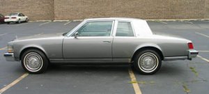
Technical information about the '76 to '79 Cadillac Seville. Subjects are "EFI Diagnosis", "'76 - '79 body parts", "Frame diagram" and "Electrical troubleshooting".

| Ref. | Dimension | Ref. | Dimension | |||
| A | 50-15/16" | Center of outboard retainer screw of no. 1 mount (radiator cradle) located approximately 5" rearward of front of frame to center of outboard retainer screw on opposite side of body. NOTE: Removal of anchor nut, large washer and lower rubber pad may be required to gain access to center of retainer screw. |
a | 15” | Center of outboard retainer screw of no.1 mount (radiator cradle) located approximately 5" rearward of front of frame. NOTE: Removal of anchor nut, large washer and lower rubber pad may be required to gain access to center of retainer screw. |
|
| B | 38-1/4” | Center of outboard retainer screw of no. 1 mount (radiator cradle) and center of master gage hole adjacent to no. 2 body mount on same side of body. | b | 9-3/4” | Center of 5/8" master gage hole adjacent to no. 2 body mount. | |
| C | 61-1/8” | Center of outboard retainer screw of no. 1 mount (radiator cradle) and center of 5/8” master gage hole adjacent to no. 2 body mount on opposite side of body. | c | 4” | Center of rearmost retainer screw at no. 3 body mount (Fig. 3-12). | |
| D | 44-9/16” | Between centers of 5/8” master gage holes adjacent to no. 2 body mount across body. | d | 4-5/16” | Center of 5/8” master gage hole in compartment pan side rail adjacent to spring front support. | |
| E | 71-3/4” | Center of 5/8” master gage hole adjacent to no. 2 body mount and center of 5/8” master gage hole in compartment pan side rail on same side of body adjacent to spring front support. | e | 15-3/4” | Lower surface of compartment pan side rail at kick-up rear of rear axle housing (30-1/2” forward of center of hole “f”). | |
| F | 69-3/4” | Center of outboard retainer screw of no. 1 mount (radiator cradle) and center of rearmost retainer screw at no. 3 body mount on same side of body (Fig. 3.12). | f | 11-1/2” | Center of 3/4” hole in compartment pan side rail approximately 10” rearward of center of rear shackle attaching bolt to frame. | |
| G | 34-1/4” | Between centers of rearmost retainer srews at no. 3 body mounts across body (Fig. 3-12). | g | 11-1/16” | Bottom surface of dash brace adjacent to no. 2 body mount (on body). | |
| H | 81-1/2” | Center of 5/8" master gage hole adjacent to no. 2 body mount and center 5/8" master gage hole in compartment pan side rail on opposite side of body adjacent to spring support. | h | 4-4/16” | Bottom surface of body floor pan side rail at rear edge of stub frame (on body). | |
| I | 33-5/16” | Between centers of 5/8” master gage holes in compartment pan side rails across body adjacent to spring front supports. | ||||
| J | 75-3/4” | Center of 5/8” master gage hole in compartment pan side rail adjacent to spring front support to center of 3/4” gage hole in compartment pan side rail on opposite side of body approximately 10” rearward of rear shackle attaching bolt to frame. NOTE: Adjust pointer and lever bar if required. |
||||
| K | 64-13/16” | Center of 5/8” master gage hole in compartment pan side rail adjacent to spring front support and center of 3/4” hole in compartment pan side rail on same side of body approximately 10” rearward of rear shackle attaching bolt to frame. | ||||
| L | 45-1/4” | Between center (front or rear edge) of 3/4” holes in compartment pan side rails approximately 10” rearward of center of rear shackle attaching bolt to frame. |